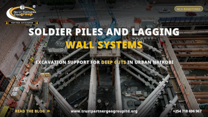
Soldier Pile and Lagging Wall Systems: Excavation Support for Deep Cuts in Urban Nairobi
Steel soldier piles, timber & steel lagging, deep excavation support & staged shoring for basements, road cuts & hillside construction in Upper Hill, Kilimani, Westlands & across Kenya
Table of Contents
- 1. What Are Soldier Pile and Lagging Walls?
- 2. When to Choose Soldier Pile & Lagging Over Sheet Piles
- 3. Soldier Pile Types and Section Selection
- 4. Lagging Materials: Timber vs. Steel vs. Shotcrete
- 5. Design: Embedment, Spacing and Bracing
- 6. Installation Sequence for Urban Nairobi
- 7. Excavation in Stages: The Critical Lift Cycle
- 8. Groundwater and Dewatering with Soldier Piles
- 9. Noise, Vibration and Neighbour Management
- 10. Equipment and Labour Requirements
- 11. NEMA, NCA and County Compliance
- 12. Construction Costs and Programme [2026]
- 13. Frequently Asked Questions
- 14. Conclusion
On a tight Nairobi plot in Kilimani where the neighbouring foundation sits 1.5 metres from your boundary, or along a hillside road cut in Kiambu where laterite boulders make continuous sheet pile driving impossible, the soldier pile and lagging wall becomes the pragmatic alternative. Unlike the continuous steel curtain of sheet piles, a soldier pile system uses discrete vertical steel H-piles or I-beams at intervals, with horizontal lagging panels spanning between them to retain the soil as excavation proceeds in controlled lifts. It is cheaper than sheet piling for medium depths, more tolerant of boulder-filled ground, and demands less crane access - making it ideal for Nairobi's congested commercial and residential redevelopment sites. This guide covers the full soldier pile wall Nairobi sequence: pile types, lagging materials, staged installation, bracing design, dewatering and 2026 costs for deep excavation support across Kenya's capital.
Trust Partners Geo-Group Ltd - Engineering Team
NCA-registered excavation & civil engineering contractor with 15+ years of basement excavation, soldier pile shoring, lagging wall installation and deep earth retention experience across East Africa. Reviewed by registered engineers.
1. What Are Soldier Pile and Lagging Walls?
A soldier pile and lagging wall - also known as a Berlin wall or king-post wall - is a discontinuous retaining system comprising two elements:
- Soldier piles: vertical steel structural sections (typically universal columns, H-piles or I-beams) installed at regular horizontal spacing along the excavation line. These piles are driven, drilled or pre-augered into the ground to an embedment depth below the final excavation level;
- Lagging: horizontal panels of timber, steel plate or shotcrete placed between the exposed flanges of adjacent soldier piles as the excavation proceeds downward in stages. The lagging retains the soil between the piles and transfers earth pressure to the soldier piles.
The system is fundamentally different from a sheet pile wall. Where sheet piles form a continuous interlocking barrier driven before excavation, soldier piles are discrete vertical columns with open gaps between them that are closed progressively by lagging as each lift of soil is removed. This discontinuous nature makes soldier piles less effective as a groundwater cut-off, but more adaptable to sites with boulders, variable soil, or restricted access where a 70-tonne sheet pile crane cannot operate.
In Nairobi, soldier pile and lagging walls are used for:
- Basement excavations of 4-10 metres on plots with boulder-filled volcanic soils;
- Road-widening and hillside cuttings where the retained face is temporary;
- Utility trenches and service corridors in dense urban areas;
- Building extensions and additions where the existing structure must be underpinned or protected.
2. When to Choose Soldier Pile & Lagging Over Sheet Piles
The choice between soldier pile and lagging versus sheet pile walls is not about which is "better" - it is about which matches the site constraints. Soldier piles win in specific Nairobi conditions:
| Condition | Soldier Pile & Lagging | Sheet Piles |
|---|---|---|
| Boulder-filled ground | Excellent - pre-auger around obstructions | Poor - refusal on boulders common |
| Groundwater | Requires dewatering - not a cut-off | Good cut-off with interlocks |
| Crane access | Smaller rig or excavator-mounted | Requires 50-100t crawler crane |
| Depth 4-8m | Cheaper and faster | Over-engineered for shallow cuts |
| Depth 10m+ | Uneconomical - bracing gets complex | Preferred for deep basements |
| Permanent wall | Shotcrete lagging can be permanent | Requires facing or is permanent steel |
| Reusability | Steel lagging and piles reusable | Sheet piles fully reusable |
| Urban noise | Less continuous driving noise | Vibratory or impact driving required |
Selection guidance for Nairobi:
- Mixed volcanic soils with laterite boulders (Kilimani, Karen, parts of Westlands): soldier piles are often the only feasible option because sheet piles refuse on boulders and pre-augering every sheet is uneconomical;
- Tight sites with no crane access (narrow lanes in Upper Hill): excavator-mounted auger rigs can install soldier piles where a crawler crane for sheet piles cannot fit;
- Medium-depth temporary excavations (4-8 metres): soldier piles with timber lagging are typically 20-30% cheaper than sheet piling for the same depth;
- High groundwater with no dewatering budget: sheet piles are preferred because soldier pile gaps allow significant water ingress without continuous pumping;
- Deep basements over 10 metres with multiple bracing levels: sheet piles or diaphragm walls are more cost-effective - soldier pile bracing at three levels becomes a maze of steel that obstructs construction.
3. Soldier Pile Types and Section Selection
The soldier pile is the structural backbone of the system. It must resist the bending moment from the retained soil and any surcharge, while achieving sufficient embedment below excavation level to prevent rotation or kick-out.
Steel Section Types
| Section | Profile | Typical Use | Depth Range |
|---|---|---|---|
| Universal Column (UC) 203x203 | Medium H-section, moderate section modulus | Shallow excavations, light surcharge | Up to 5m |
| Universal Column (UC) 254x254 | Heavy H-section, high section modulus | Medium basements, road cuts | 5-8m |
| Universal Column (UC) 305x305 | Very heavy H-section | Deep cuts, heavy surcharge | 8-12m |
| HEB / IPE Sections | European wide-flange beams | Imported projects, specific specs | Variable |
| Steel Pipe (king piles) | Circular hollow section | Combined with sheet infill | 10-20m+ |
Steel grades are typically S355JR or S275JR, with hot-dip galvanizing for permanent applications or painted protection for temporary works. In Nairobi, UC 254x254 and UC 305x305 are the most common sections for commercial basement and road-cut applications because they balance availability, section modulus, and weight (which affects the crane or rig capacity needed for installation).
Pile Spacing
Horizontal spacing between soldier piles is determined by the span capability of the lagging material and the soil arching effect. Typical spacings are:
- Timber lagging: 1.5-2.5 metres (timber planks can span only limited distances before excessive bending);
- Steel plate lagging: 2.0-3.0 metres (steel plates span further but deflection must be checked);
- Shotcrete lagging: 2.5-3.5 metres (shotcrete acts as a continuous arch between piles but requires close spacing for thick application).
Embedment Depth
Soldier pile embedment is typically 1.0 to 1.5 times the excavation depth below final level for cantilever walls, reducing to 0.8-1.2 times for propped or strutted walls. For a 6-metre deep excavation, piles extend 6-9 metres below excavation level, giving total lengths of 12-15 metres. In Nairobi's volcanic soils, refusal on dense tuff or weathered basalt often governs the practical embedment depth.
4. Lagging Materials: Timber vs. Steel vs. Shotcrete
The lagging is the horizontal element that spans between soldier piles and retains the soil. Its material choice affects cost, durability, water tolerance, and whether the wall can be permanent.
Timber Lagging
Traditional timber lagging uses treated hardwood planks (typically 200mm x 50mm or 250mm x 50mm) wedged horizontally between the flanges of adjacent soldier piles as each excavation lift is exposed. Advantages include low cost, easy site cutting to fit irregular gaps, and light weight. Disadvantages include rot when wet, termite attack in Nairobi's climate, limited reuse, and restricted span (typically 1.5-2.5m pile spacing). Timber lagging is best for dry, temporary excavations under 6 metres where the wall will be backfilled within 6-12 months.
Steel Plate Lagging
Steel plate lagging uses pre-drilled steel plates (6-10mm thick, 200-300mm deep) bolted or welded to the webs of adjacent soldier piles. Advantages include reusability, strength, no rot or termite risk, and longer spans between piles. Disadvantages include higher cost, heavier handling, and the need for precise pre-drilling to match pile spacing. Steel lagging is the default for urban Nairobi projects where timber rot, groundwater, and reuse economics make timber uncompetitive.
Shotcrete Lagging
Shotcrete lagging involves welding wire mesh to the soldier piles and spraying 75-100mm of concrete onto the exposed soil face between piles as excavation proceeds. Advantages include a permanent structural facing, excellent durability, and the ability to incorporate drainage weep holes. Disadvantages include the need for a concrete pump and skilled nozzlemen, curing time, and higher initial cost. Shotcrete lagging is used where the wall face must remain exposed permanently - such as basement walls, permanent road cuts, or hillside retaining structures.
| Lagging Type | Cost/m2 | Max Span | Water Tolerance | Reusable | Best For |
|---|---|---|---|---|---|
| Timber | KES 800-1,500 | 2.0m | Poor - rots when wet | No | Dry, temporary, shallow |
| Steel plate | KES 1,500-2,500 | 3.0m | Good - galvanised | Yes | Urban, medium depth, wet |
| Shotcrete | KES 2,500-4,000 | 3.5m | Excellent | No | Permanent walls, deep cuts |
5. Design: Embedment, Spacing and Bracing
The geotechnical engineer designs the soldier pile and lagging system based on the same parameters as any retaining wall, with additional focus on the lagging span and pile spacing interaction:
- Excavation depth: the primary driver of pile bending moment, embedment requirement, and bracing levels;
- Soil properties: friction angle, cohesion, and density of the retained soil and the founding stratum. Nairobi's laterite and volcanic tuff have high friction angles (30-40 degrees) but variable cohesion;
- Groundwater: water table level and flow rate - soldier piles are not a cut-off, so dewatering design is integral;
- Surcharge: loads from adjacent buildings, roads, stockpiles or construction equipment. Upper Hill commercial towers impose heavy surcharge;
- Lagging span: the horizontal distance between pile centres determines lagging thickness and material;
- Deflection limits: adjacent structures may tolerate only 15-30mm of lateral movement at ground level.
Earth Pressure on Lagging
The lagging between piles is designed for the earth pressure acting on the tributary width (half the spacing to each adjacent pile). For a pile spacing of 2.0 metres, each metre of lagging height supports a 2.0-metre width of retained soil. The pressure distribution is typically triangular, increasing with depth. At 6 metres depth, the horizontal earth pressure in medium-dense Nairobi laterite is approximately 25-40 kPa, requiring steel plate lagging of at least 8mm thickness or timber of 250mm depth.
Bracing Levels
For excavations deeper than 4-5 metres, cantilever soldier piles become uneconomical. Internal bracing (walers and struts) or ground anchors are required. Typical strut spacing for soldier pile walls is 3-4 metres vertically and 4-6 metres horizontally. The excavation proceeds in stages: dig 1.2-1.5 metres, install lagging, dig to next bracing level, install waler and struts, and repeat.
Critical rule: lagging must follow the dig
The most dangerous moment in soldier pile and lagging construction is the gap between excavating a lift and installing the lagging. Unsupported soil between piles can slough, creating voids behind the wall that lead to ground settlement and adjacent building damage. The specification must require lagging installation within 4 hours of exposing each lift - not the next morning. On Nairobi sites with sandy or loose fill layers, this interval may need to be 2 hours or less.
6. Installation Sequence for Urban Nairobi
Soldier pile installation in Nairobi follows a disciplined sequence that minimises vibration, manages spoil, and protects adjacent structures:
Step 1: Site Setup and Pile Layout
The excavation line is marked with survey pegs. Pile positions are set out at the design spacing (typically 2.0-2.5m for steel lagging). In dense urban areas, the set-out must account for underground services - Nairobi's older districts (Parklands, Eastleigh, Industrial Area) have unmapped water, sewer and power cables that can obstruct pile positions.
Step 2: Pre-Augering or Drilling
Where dense laterite, tuff or boulders are present - which is the norm in Nairobi - piles are installed by pre-augering. A hydraulic auger rig drills holes of 300-500mm diameter to the design embedment depth (typically 12-18 metres total). The hole is inspected for depth and alignment, then the steel pile is lowered in and backfilled with lean concrete (C15-C20) or grout to secure it. In softer soils, piles may be driven with a vibratory hammer mounted on an excavator.
Step 3: Capping Beam or Ground Waler
A reinforced concrete capping beam is cast at ground level connecting all pile heads, or a steel ground waler is bolted across the pile tops. This beam distributes surcharge loads, provides a fixing point for the top level of lagging, and acts as a benchmark for excavation levels. In Nairobi, the capping beam is typically 300mm wide x 400mm deep in C25 concrete with starter bars into the piles.
Step 4: Excavation and Lagging Commencement
Excavation begins in controlled lifts, with lagging installed immediately after each lift is exposed. The sequence is critical: excavate, lag, excavate, lag - never excavate two lifts ahead of the lagging.
7. Excavation in Stages: The Critical Lift Cycle
The staged excavation cycle is the heart of soldier pile and lagging construction. Each lift must be shallow enough that the exposed soil between piles remains stable long enough for lagging to be installed, but deep enough to maintain construction efficiency.
Lift Height
Standard lift heights are 1.2-1.5 metres for timber lagging and 1.5-2.0 metres for steel or shotcrete lagging. In cohesive Nairobi clay or dense laterite, lifts of 2.0 metres may be stable temporarily. In loose fill or sandy soils, lifts must be reduced to 1.0-1.2 metres. The geotechnical engineer specifies the maximum unsupported lift height in the temporary works design.
The Lift Cycle
- Excavate to the next lagging level using an excavator working from the surface (for the first lift) or from within the excavation (for lower lifts);
- Trim the excavation face vertically between piles, removing loose soil and overhangs;
- Install lagging panels, wedging them tightly against the soil and ensuring full bearing on the pile flanges;
- For shotcrete lagging: weld mesh, install weep holes, and spray concrete to the specified thickness;
- Record lagging installation, pile deflection, and any seepage or soil loss;
- Proceed to the next lift only after the lagging is secured and any required bracing is installed.
Bracing Installation Sequence
For deep excavations, bracing is installed at designated levels before excavation proceeds below that level. A typical 8-metre deep basement with two levels of bracing follows: excavate to 2.0m, install lagging, excavate to 4.0m, install lagging and first waler/strut level, excavate to 6.0m, install lagging, excavate to 8.0m, install lagging and second waler/strut level. Pre-loading struts with hydraulic jacks reduces wall deflection by 30-50% compared with hand-tightened connections.
8. Groundwater and Dewatering with Soldier Piles
Soldier pile and lagging walls are inherently permeable. Unlike sheet piles, which form a near-continuous barrier, soldier piles have significant gaps between them that allow groundwater to flow freely into the excavation. Dewatering is therefore not optional - it is a structural requirement.
Water Ingress Paths
- Between lagging panels: even tightly wedged timber or steel lagging leaves gaps where water seeps through. In high-flow conditions, these gaps can erode soil behind the wall, creating voids;
- Around pile flanges: the space between the pile web and the soil is a preferential flow path, especially where piles are installed in augered holes with imperfect backfill;
- Below pile toe: if the pile embedment is above the impermeable layer, water flows beneath the wall into the excavation.
Dewatering Methods
| Method | Application | Typical Cost |
|---|---|---|
| Wellpoint system | Shallow excavations (<6m), sandy soils | KES 80,000-150,000/month |
| Deep well system | Deep excavations (>6m), high flow | KES 150,000-300,000/month |
| Sump pumping | Minor seepage, clay soils | KES 30,000-60,000/month |
| Geotextile filter | Behind timber lagging to prevent soil loss | KES 150-300/m2 |
In Nairobi's highland areas with deep groundwater (parts of Karen, Langata, Kitisuru), dewatering may be minimal or unnecessary. In low-lying areas with shallow water tables (Industrial Area, parts of Westlands near the river, riparian zones), continuous wellpoint dewatering is essential from day one of excavation. Discharge must comply with NEMA and WRA requirements, with sediment traps mandatory before release to stormwater systems.
9. Noise, Vibration and Neighbour Management
Urban Nairobi construction operates under strict noise and vibration constraints that affect soldier pile installation methods:
- Noise limits: Nairobi County restricts construction noise to 70 dB daytime and 60 dB nighttime at the site boundary. Pre-augering for soldier piles produces 75-90 dB - manageable with standard barriers. Impact driving of piles (where used) produces 100-120 dB and is increasingly restricted;
- Vibration limits: peak particle velocity of 5 mm/s for residential buildings, 10 mm/s for commercial. Pre-augering generates minimal vibration (1-3 mm/s PPV). Vibratory pile driving generates 5-15 mm/s and may require pre-augering in sensitive areas;
- Working hours: noisy construction is typically restricted to 07:30-17:30 weekdays and 08:00-13:00 Saturdays. Soldier pile pre-augering can often continue within these hours without special permit;
- Adjacent building protection: pre-construction condition surveys, settlement markers, and vibration monitors on neighbouring structures are standard for excavations over 4 metres deep near buildings. Trust Partners Geo-Group Ltd provides third-party monitoring as part of our urban excavation package.
Because soldier pile installation is less continuous than sheet pile driving - augering one hole, placing one pile, then moving to the next - the noise profile is intermittent rather than the sustained drone of a vibratory hammer. This makes neighbour relations easier to manage, particularly on residential streets in Kilimani and Lavington where complaints can trigger county enforcement.
10. Equipment and Labour Requirements
The equipment fleet for soldier pile wall Nairobi projects is lighter than for sheet piling, making it suitable for confined sites:
| Equipment | Role | Typical Specification |
|---|---|---|
| Hydraulic auger rig | Drilling soldier pile holes | 300-500mm auger, 15-25m depth, 20-30t rig |
| Excavator with auger attachment | Shorter piles in confined sites | 20-30 tonne, 400mm auger |
| Crawler crane or mobile crane | Lifting and placing piles | 30-50 tonne, 20-30m boom |
| Excavator | Staged excavation in lifts | 20-30 tonne with bucket and breaker |
| Shotcrete pump and nozzle | Sprayed concrete lagging | Concrete pump, 5-10 m3/hr |
| Welding set | Splicing piles, attaching brackets | 400A MMA or MIG |
| Dewatering pumps | Groundwater control | Submersible, 5-15 kW |
| Vibratory hammer (optional) | Driving piles in soft ground | Excavator-mounted, 150-250 kW |
Labour requirements are significant. A typical soldier pile crew includes: a piling rig operator, a crane operator, a dogman/slinger, two steel fixers/welders, three excavation labourers, a shotcrete nozzlemen team (if applicable), and a site engineer or foreman monitoring alignment and lagging quality. For a 40-metre wall, the installation and first-lift excavation phase takes 5-8 working days.
11. NEMA, NCA and County Compliance
Soldier pile and lagging projects in Kenya trigger the same regulatory framework as other deep excavation systems:
| Requirement | Authority | What It Covers |
|---|---|---|
| Building plan approval | County government | Structural drawings, shoring design, excavation levels |
| NEMA approval | NEMA | Noise, dewatering discharge, EMP for deep excavations |
| NCA registration | National Construction Authority | Contractor registration, site safety, temporary works |
| Traffic / road reserve | KeNHA / KURA / County | Rig positioning, hoarding, road space |
| Water discharge permit | Water Resources Authority | Dewatering discharge to stormwater or sewer |
| Adjacent building consent | Civil / County | Party wall agreements, monitoring access |
The temporary works (soldier piles, lagging, walers, struts) must be designed by a registered structural or geotechnical engineer and inspected before excavation proceeds below each bracing level. County building inspectors may require hold points at each lagging level for excavations over 6 metres deep. Third-party monitoring of adjacent buildings is increasingly required by insurers and county authorities for urban deep-cut projects.
12. Construction Costs and Programme [2026]
Indicative costs for soldier pile and lagging wall installation and deep excavation support in Kenya:
| Item | 2026 Rate | Notes |
|---|---|---|
| Steel soldier pile rental | KES 3,500-5,500/m/month | Per linear metre; purchase KES 8,000-12,000/m |
| Pile installation (pre-augered) | KES 4,000-8,000/m2 | Wall face area, including augering and backfill |
| Pile installation (driven) | KES 3,000-6,000/m2 | Soft ground only; less common in Nairobi |
| Timber lagging supply & install | KES 800-1,500/m2 | Wall face area; not reusable |
| Steel plate lagging supply & install | KES 1,500-2,500/m2 | Reusable; galvanised |
| Shotcrete lagging with mesh | KES 2,500-4,000/m2 | Includes weep holes and curing |
| Capping beam (concrete) | KES 8,000-15,000/m | Per metre of wall, including rebar and formwork |
| Waler and strut supply & install | KES 2,500-5,000/m2 | Of shored wall face |
| Dewatering system | KES 80,000-250,000/month | Wellpoints or deep wells |
| Third-party monitoring | KES 50,000-120,000/month | Adjacent building settlement and vibration |
| Mobilization / demobilization | KES 100,000-250,000 | Auger rig, crane, transport |
All-in project estimates (per 100 linear metres of wall):
- 5m deep, timber lagging, cantilever: KES 1.8-3.0 million;
- 6m deep, steel lagging, one strut level: KES 2.5-4.5 million;
- 8m deep, shotcrete lagging, two strut levels: KES 4.5-7.5 million;
- 10m deep, steel lagging, three strut levels: KES 6.5-10.5 million.
Programme: mobilization 1-2 days; pile installation 3-5 days for a standard wall; excavation and lagging 1-2 weeks depending on depth and lift cycle; bracing installation 2-3 days per level; demobilization 1-2 days. Total programme for a 6-metre deep basement with one strut level is typically 3-4 weeks from mobilization to final lagging level.
Pro tip: steel lagging pays back on reuse
Steel plate lagging costs 30-40% more than timber upfront, but on projects where Trust Partners Geo-Group Ltd manages multiple phases or adjacent plots, the steel lagging is recovered, cleaned, and reused. Over three projects, steel lagging becomes cheaper than timber while eliminating rot, termite, and groundwater degradation risks. We maintain a steel lagging inventory for repeat clients in Upper Hill and Westlands.
13. Frequently Asked Questions: Soldier Pile and Lagging Walls in Kenya
What is a soldier pile and lagging wall system and when is it used?
A soldier pile and lagging wall is a discontinuous retaining system consisting of vertical steel H-piles or I-beams (soldier piles) installed at regular intervals, with horizontal timber, steel or shotcrete panels (lagging) placed between them to retain the soil. It is used for deep excavations of 4-12 metres in urban areas where sheet pile driving is impractical due to boulders or dense refusal, where groundwater is manageable with dewatering, or where cost savings are needed for medium-depth temporary shoring. In Nairobi, soldier pile and lagging walls are common on hillside sites in Kilimani, Upper Hill road-widening projects, and basement excavations where mixed volcanic soils with laterite boulders make continuous sheet pile penetration difficult.
What is the difference between soldier pile and lagging and sheet pile walls?
Sheet pile walls are continuous interlocking steel barriers driven or vibrated into the ground, forming a watertight-ish wall ideal for deep basements with groundwater. Soldier pile and lagging walls are discontinuous: vertical steel piles at 1.5-3.0 metre centres with horizontal lagging panels between them. Soldier piles tolerate boulder-filled ground better because individual piles can be pre-augered or drilled, and lagging is placed after excavation begins. Sheet piles are faster to install and better for groundwater cut-off; soldier piles are cheaper for medium depths, more adaptable to obstructions, and require less heavy crane access. In Nairobi's volcanic soils with scattered tuff boulders, soldier piles are often the only feasible option where sheet piles would refuse.
How deep can soldier pile and lagging walls support excavation in Nairobi?
Soldier pile and lagging walls in Nairobi typically support excavations from 4 metres to 12 metres deep. For depths under 5 metres, cantilever soldier piles with timber or steel lagging are economical. For 5-8 metres, one level of waler and strut bracing is required. For 8-12 metres, two or three levels of bracing are needed, and the soldier piles must be heavy H-sections (HEB 400 or larger) with embedment of 1.0-1.5 times the excavation depth below final level. Depths beyond 12 metres are generally uneconomical for soldier pile systems and diaphragm walls or secant piles are preferred. The practical limit in Nairobi is often set by the ability to achieve pile embedment into dense tuff or weathered rock.
What does soldier pile and lagging wall installation cost in Kenya in 2026?
2026 indicative costs for soldier pile and lagging in Kenya: steel soldier pile supply (rental) KES 3,500-5,500 per linear metre per month; pile installation by pre-augering and placement KES 4,000-8,000 per m2 of wall face; timber lagging supply and install KES 800-1,500 per m2; steel plate lagging KES 1,500-2,500 per m2; shotcrete lagging with mesh KES 2,500-4,000 per m2; waler and strut bracing KES 2,500-5,000 per m2; dewatering system KES 80,000-200,000 per month. A typical 6-metre deep, 40-metre long soldier pile wall with timber lagging and one strut level costs KES 2.5-4.5 million for installation, excluding monthly pile rental until backfill is complete. Steel lagging adds 30-40% to lagging costs but is reusable.
How is groundwater controlled with soldier pile and lagging walls?
Soldier pile and lagging walls are not waterproof - significant gaps exist between the lagging panels and around pile flanges. Groundwater control relies on: continuous dewatering inside the excavation using wellpoints, deep wells or sump pumps to lower the water table below excavation level; placing geotextile filter fabric behind timber lagging to prevent soil wash-through while allowing water to drain to the dewatering system; sealing pile interstices with bentonite or grout where seepage is concentrated; and accepting minor seepage through the lagging in low-flow conditions with sump pumping. In Nairobi's highland areas with deep groundwater, dewatering may be minimal. Near springs or in saturated zones (Karen, parts of Westlands), continuous wellpoint dewatering is essential and the design must account for hydrostatic pressure on the back of the lagging.
What lagging material is best for soldier pile walls in Kenya?
The best lagging material depends on excavation depth, groundwater, permanence, and budget. Timber lagging (treated hardwood, 200x50mm or 250x50mm planks) is cheapest and easiest to cut on site, ideal for temporary works under 6 metres and dry conditions, but it rots if wet and cannot be reused. Steel plate lagging (6-10mm thick, pre-drilled) is reusable, stronger, and better for deeper excavations and wet conditions, but costs 30-40% more than timber. Shotcrete lagging (75-100mm sprayed concrete over wire mesh welded to piles) provides a permanent structural facing, excellent durability, and can incorporate drainage weep holes, but requires a concrete pump, skilled nozzlemen, and curing time. For most Nairobi basement projects, steel lagging is the default for urban sites where timber rot and termite risk are concerns; shotcrete is used where the wall face must remain exposed permanently.
What equipment is used for soldier pile installation in Kenya?
Soldier pile installation in Kenya uses: hydraulic piling rigs or auger rigs (300-600mm diameter) to drill or pre-auger holes to embedment depth; crawler cranes or large excavators to lift and place H-piles or I-beams into the holes; concrete pumps and shotcrete rigs if shotcrete lagging is specified; welding equipment for splicing piles and attaching waler brackets; dewatering pumps (submersible, 5-15 kW) for groundwater control; and standard excavators for the staged excavation in lifts. For driven soldier piles in softer ground, impact hammers or vibratory hammers mounted on excavators are used. Unlike sheet pile installation, soldier pile work does not always require a 70-tonne crawler crane, making it suitable for confined Nairobi plots with limited access.
Do soldier pile and lagging walls need building approval in Kenya?
Yes. Deep excavation with soldier pile and lagging shoring requires county building plan approval including structural drawings for the temporary works. NEMA approval may be required if the excavation involves significant dewatering, discharge to stormwater systems, or operation near sensitive receptors. NCA-registered contractors must execute the works, and a registered structural or geotechnical engineer must design and certify the shoring system, calculating pile embedment, lagging bending, and bracing loads. For excavations over 6 metres deep or adjacent to roads and buildings, the county may require a method statement, dewatering plan, excavation sequence, and third-party monitoring of adjacent structures. KeNHA or KURA approval is needed if the works encroach on road reserves. Insurance and third-party liability coverage are standard requirements.
14. Conclusion: Piles, Planks and Patience
A soldier pile and lagging wall is not a second-best alternative to sheet piling - it is a deliberate choice for specific ground conditions, access constraints, and economic parameters. Where Nairobi's volcanic soils throw boulders that would stop a sheet pile cold, the soldier pile simply augers past the obstruction and stands firm. Where a 70-tonne crane cannot fit down a Kilimani lane, an excavator-mounted auger installs the piles one by one. Where a developer needs medium-depth shoring at medium cost, timber or steel lagging delivers without the rental burden of continuous steel sheets.
But the system demands discipline. The lagging must follow the dig within hours, not days. The dewatering must run continuously, because the wall is not a cut-off. The bracing must be pre-loaded before the next lift is excavated. The soldier pile contractor who treats lagging as an afterthought invites collapse; the contractor who treats each lift as a structural event builds a safe wall.
Trust Partners Geo-Group Ltd delivers the full soldier pile and lagging package across Kenya: pile installation by pre-augering or driving, timber and steel lagging supply and placement, shotcrete lagging with mesh and weep holes, waler and strut bracing systems, dewatering coordination, staged excavation management, and third-party monitoring of adjacent structures. We work with your geotechnical engineer's design, manage NEMA and county compliance, and deliver safe deep excavations in Nairobi's tightest urban sites - on unit-rate or lump-sum contracts, with NCA-registered crews and specialist piling equipment.
Soldier Pile & Lagging Wall Installation
Deep excavation shoring, soldier pile installation, timber & steel lagging, shotcrete facing, waler and strut systems, and dewatering for deep cuts across Nairobi and Kenya.
Free lead magnet: ask for our Deep Excavation Shoring Checklist (PDF) - soldier pile hold points, lagging installation records, bracing load tests and dewatering logs your structural engineer will require.
Related Resources
Sheet Pile Wall Installation for Basement Excavation in Nairobi: Driven vs. Vibratory Methods
The continuous steel alternative - interlocking sheet piles for deep basements with groundwater control.
READ MOREReinforced Earth Retaining Walls for Road Projects: MSE Wall Excavation & Installation
Mechanically stabilized earth walls for highways and road projects across Kenya.
READ MOREBorrow Pit Excavation in Kenya: Sourcing Fill Materials for Roads and Building Projects
Approved borrow pits, fill material sourcing and earth fill logistics for construction sites.
READ MOREEarthworks QA/QC: Compaction Testing & Density Control
The layer-by-layer testing regime for excavation backfill and shoring earthworks.
READ MORESlope Excavation and Stabilization for Hillside Construction in Nairobi & Kiambu
Cut slopes, benching and stabilization techniques for hillside building and road projects.
READ MOREPile Foundation Excavation in Kenya: Bored Piles vs. Driven Piles [2026 Guide]
Deep foundation excavation methods for high-rise buildings and heavy structures.
READ MORETRUST PARTNERS GEO-GROUP LTD | YOUR VISION, OUR EXCAVATION
WEBSITE: WWW.TRUSTPARTNERGEOGROUPLTD.ORG | EMAIL: INFO@TRUSTPARTNERGEOGROUPLTD.ORG | PHONE: +254 718 68 69 67
FOLLOW US: FACEBOOK | TIKTOK | INSTAGRAM | YOUTUBE | LINKEDIN
© 2026 TRUST PARTNERS GEO-GROUP LTD. ALL RIGHTS RESERVED.
Soldier Pile and Lagging Wall Systems: Excavation Support for Deep Cuts in Urban Nairobi
Steel soldier piles, timber & steel lagging, deep excavation support & staged shoring for basements, road cuts & hillside construction in Upper Hill, Kilimani, Westlands & across Kenya
Table of Contents
- 1. What Are Soldier Pile and Lagging Walls?
- 2. When to Choose Soldier Pile & Lagging Over Sheet Piles
- 3. Soldier Pile Types and Section Selection
- 4. Lagging Materials: Timber vs. Steel vs. Shotcrete
- 5. Design: Embedment, Spacing and Bracing
- 6. Installation Sequence for Urban Nairobi
- 7. Excavation in Stages: The Critical Lift Cycle
- 8. Groundwater and Dewatering with Soldier Piles
- 9. Noise, Vibration and Neighbour Management
- 10. Equipment and Labour Requirements
- 11. NEMA, NCA and County Compliance
- 12. Construction Costs and Programme [2026]
- 13. Frequently Asked Questions
- 14. Conclusion
On a tight Nairobi plot in Kilimani where the neighbouring foundation sits 1.5 metres from your boundary, or along a hillside road cut in Kiambu where laterite boulders make continuous sheet pile driving impossible, the soldier pile and lagging wall becomes the pragmatic alternative. Unlike the continuous steel curtain of sheet piles, a soldier pile system uses discrete vertical steel H-piles or I-beams at intervals, with horizontal lagging panels spanning between them to retain the soil as excavation proceeds in controlled lifts. It is cheaper than sheet piling for medium depths, more tolerant of boulder-filled ground, and demands less crane access - making it ideal for Nairobi's congested commercial and residential redevelopment sites. This guide covers the full soldier pile wall Nairobi sequence: pile types, lagging materials, staged installation, bracing design, dewatering and 2026 costs for deep excavation support across Kenya's capital.
Trust Partners Geo-Group Ltd - Engineering Team
NCA-registered excavation & civil engineering contractor with 15+ years of basement excavation, soldier pile shoring, lagging wall installation and deep earth retention experience across East Africa. Reviewed by registered engineers.
1. What Are Soldier Pile and Lagging Walls?
A soldier pile and lagging wall - also known as a Berlin wall or king-post wall - is a discontinuous retaining system comprising two elements:
- Soldier piles: vertical steel structural sections (typically universal columns, H-piles or I-beams) installed at regular horizontal spacing along the excavation line. These piles are driven, drilled or pre-augered into the ground to an embedment depth below the final excavation level;
- Lagging: horizontal panels of timber, steel plate or shotcrete placed between the exposed flanges of adjacent soldier piles as the excavation proceeds downward in stages. The lagging retains the soil between the piles and transfers earth pressure to the soldier piles.
The system is fundamentally different from a sheet pile wall. Where sheet piles form a continuous interlocking barrier driven before excavation, soldier piles are discrete vertical columns with open gaps between them that are closed progressively by lagging as each lift of soil is removed. This discontinuous nature makes soldier piles less effective as a groundwater cut-off, but more adaptable to sites with boulders, variable soil, or restricted access where a 70-tonne sheet pile crane cannot operate.
In Nairobi, soldier pile and lagging walls are used for:
- Basement excavations of 4-10 metres on plots with boulder-filled volcanic soils;
- Road-widening and hillside cuttings where the retained face is temporary;
- Utility trenches and service corridors in dense urban areas;
- Building extensions and additions where the existing structure must be underpinned or protected.
2. When to Choose Soldier Pile & Lagging Over Sheet Piles
The choice between soldier pile and lagging versus sheet pile walls is not about which is "better" - it is about which matches the site constraints. Soldier piles win in specific Nairobi conditions:
| Condition | Soldier Pile & Lagging | Sheet Piles |
|---|---|---|
| Boulder-filled ground | Excellent - pre-auger around obstructions | Poor - refusal on boulders common |
| Groundwater | Requires dewatering - not a cut-off | Good cut-off with interlocks |
| Crane access | Smaller rig or excavator-mounted | Requires 50-100t crawler crane |
| Depth 4-8m | Cheaper and faster | Over-engineered for shallow cuts |
| Depth 10m+ | Uneconomical - bracing gets complex | Preferred for deep basements |
| Permanent wall | Shotcrete lagging can be permanent | Requires facing or is permanent steel |
| Reusability | Steel lagging and piles reusable | Sheet piles fully reusable |
| Urban noise | Less continuous driving noise | Vibratory or impact driving required |
Selection guidance for Nairobi:
- Mixed volcanic soils with laterite boulders (Kilimani, Karen, parts of Westlands): soldier piles are often the only feasible option because sheet piles refuse on boulders and pre-augering every sheet is uneconomical;
- Tight sites with no crane access (narrow lanes in Upper Hill): excavator-mounted auger rigs can install soldier piles where a crawler crane for sheet piles cannot fit;
- Medium-depth temporary excavations (4-8 metres): soldier piles with timber lagging are typically 20-30% cheaper than sheet piling for the same depth;
- High groundwater with no dewatering budget: sheet piles are preferred because soldier pile gaps allow significant water ingress without continuous pumping;
- Deep basements over 10 metres with multiple bracing levels: sheet piles or diaphragm walls are more cost-effective - soldier pile bracing at three levels becomes a maze of steel that obstructs construction.
3. Soldier Pile Types and Section Selection
The soldier pile is the structural backbone of the system. It must resist the bending moment from the retained soil and any surcharge, while achieving sufficient embedment below excavation level to prevent rotation or kick-out.
Steel Section Types
| Section | Profile | Typical Use | Depth Range |
|---|---|---|---|
| Universal Column (UC) 203x203 | Medium H-section, moderate section modulus | Shallow excavations, light surcharge | Up to 5m |
| Universal Column (UC) 254x254 | Heavy H-section, high section modulus | Medium basements, road cuts | 5-8m |
| Universal Column (UC) 305x305 | Very heavy H-section | Deep cuts, heavy surcharge | 8-12m |
| HEB / IPE Sections | European wide-flange beams | Imported projects, specific specs | Variable |
| Steel Pipe (king piles) | Circular hollow section | Combined with sheet infill | 10-20m+ |
Steel grades are typically S355JR or S275JR, with hot-dip galvanizing for permanent applications or painted protection for temporary works. In Nairobi, UC 254x254 and UC 305x305 are the most common sections for commercial basement and road-cut applications because they balance availability, section modulus, and weight (which affects the crane or rig capacity needed for installation).
Pile Spacing
Horizontal spacing between soldier piles is determined by the span capability of the lagging material and the soil arching effect. Typical spacings are:
- Timber lagging: 1.5-2.5 metres (timber planks can span only limited distances before excessive bending);
- Steel plate lagging: 2.0-3.0 metres (steel plates span further but deflection must be checked);
- Shotcrete lagging: 2.5-3.5 metres (shotcrete acts as a continuous arch between piles but requires close spacing for thick application).
Embedment Depth
Soldier pile embedment is typically 1.0 to 1.5 times the excavation depth below final level for cantilever walls, reducing to 0.8-1.2 times for propped or strutted walls. For a 6-metre deep excavation, piles extend 6-9 metres below excavation level, giving total lengths of 12-15 metres. In Nairobi's volcanic soils, refusal on dense tuff or weathered basalt often governs the practical embedment depth.
4. Lagging Materials: Timber vs. Steel vs. Shotcrete
The lagging is the horizontal element that spans between soldier piles and retains the soil. Its material choice affects cost, durability, water tolerance, and whether the wall can be permanent.
Timber Lagging
Traditional timber lagging uses treated hardwood planks (typically 200mm x 50mm or 250mm x 50mm) wedged horizontally between the flanges of adjacent soldier piles as each excavation lift is exposed. Advantages include low cost, easy site cutting to fit irregular gaps, and light weight. Disadvantages include rot when wet, termite attack in Nairobi's climate, limited reuse, and restricted span (typically 1.5-2.5m pile spacing). Timber lagging is best for dry, temporary excavations under 6 metres where the wall will be backfilled within 6-12 months.
Steel Plate Lagging
Steel plate lagging uses pre-drilled steel plates (6-10mm thick, 200-300mm deep) bolted or welded to the webs of adjacent soldier piles. Advantages include reusability, strength, no rot or termite risk, and longer spans between piles. Disadvantages include higher cost, heavier handling, and the need for precise pre-drilling to match pile spacing. Steel lagging is the default for urban Nairobi projects where timber rot, groundwater, and reuse economics make timber uncompetitive.
Shotcrete Lagging
Shotcrete lagging involves welding wire mesh to the soldier piles and spraying 75-100mm of concrete onto the exposed soil face between piles as excavation proceeds. Advantages include a permanent structural facing, excellent durability, and the ability to incorporate drainage weep holes. Disadvantages include the need for a concrete pump and skilled nozzlemen, curing time, and higher initial cost. Shotcrete lagging is used where the wall face must remain exposed permanently - such as basement walls, permanent road cuts, or hillside retaining structures.
| Lagging Type | Cost/m2 | Max Span | Water Tolerance | Reusable | Best For |
|---|---|---|---|---|---|
| Timber | KES 800-1,500 | 2.0m | Poor - rots when wet | No | Dry, temporary, shallow |
| Steel plate | KES 1,500-2,500 | 3.0m | Good - galvanised | Yes | Urban, medium depth, wet |
| Shotcrete | KES 2,500-4,000 | 3.5m | Excellent | No | Permanent walls, deep cuts |
5. Design: Embedment, Spacing and Bracing
The geotechnical engineer designs the soldier pile and lagging system based on the same parameters as any retaining wall, with additional focus on the lagging span and pile spacing interaction:
- Excavation depth: the primary driver of pile bending moment, embedment requirement, and bracing levels;
- Soil properties: friction angle, cohesion, and density of the retained soil and the founding stratum. Nairobi's laterite and volcanic tuff have high friction angles (30-40 degrees) but variable cohesion;
- Groundwater: water table level and flow rate - soldier piles are not a cut-off, so dewatering design is integral;
- Surcharge: loads from adjacent buildings, roads, stockpiles or construction equipment. Upper Hill commercial towers impose heavy surcharge;
- Lagging span: the horizontal distance between pile centres determines lagging thickness and material;
- Deflection limits: adjacent structures may tolerate only 15-30mm of lateral movement at ground level.
Earth Pressure on Lagging
The lagging between piles is designed for the earth pressure acting on the tributary width (half the spacing to each adjacent pile). For a pile spacing of 2.0 metres, each metre of lagging height supports a 2.0-metre width of retained soil. The pressure distribution is typically triangular, increasing with depth. At 6 metres depth, the horizontal earth pressure in medium-dense Nairobi laterite is approximately 25-40 kPa, requiring steel plate lagging of at least 8mm thickness or timber of 250mm depth.
Bracing Levels
For excavations deeper than 4-5 metres, cantilever soldier piles become uneconomical. Internal bracing (walers and struts) or ground anchors are required. Typical strut spacing for soldier pile walls is 3-4 metres vertically and 4-6 metres horizontally. The excavation proceeds in stages: dig 1.2-1.5 metres, install lagging, dig to next bracing level, install waler and struts, and repeat.
Critical rule: lagging must follow the dig
The most dangerous moment in soldier pile and lagging construction is the gap between excavating a lift and installing the lagging. Unsupported soil between piles can slough, creating voids behind the wall that lead to ground settlement and adjacent building damage. The specification must require lagging installation within 4 hours of exposing each lift - not the next morning. On Nairobi sites with sandy or loose fill layers, this interval may need to be 2 hours or less.
6. Installation Sequence for Urban Nairobi
Soldier pile installation in Nairobi follows a disciplined sequence that minimises vibration, manages spoil, and protects adjacent structures:
Step 1: Site Setup and Pile Layout
The excavation line is marked with survey pegs. Pile positions are set out at the design spacing (typically 2.0-2.5m for steel lagging). In dense urban areas, the set-out must account for underground services - Nairobi's older districts (Parklands, Eastleigh, Industrial Area) have unmapped water, sewer and power cables that can obstruct pile positions.
Step 2: Pre-Augering or Drilling
Where dense laterite, tuff or boulders are present - which is the norm in Nairobi - piles are installed by pre-augering. A hydraulic auger rig drills holes of 300-500mm diameter to the design embedment depth (typically 12-18 metres total). The hole is inspected for depth and alignment, then the steel pile is lowered in and backfilled with lean concrete (C15-C20) or grout to secure it. In softer soils, piles may be driven with a vibratory hammer mounted on an excavator.
Step 3: Capping Beam or Ground Waler
A reinforced concrete capping beam is cast at ground level connecting all pile heads, or a steel ground waler is bolted across the pile tops. This beam distributes surcharge loads, provides a fixing point for the top level of lagging, and acts as a benchmark for excavation levels. In Nairobi, the capping beam is typically 300mm wide x 400mm deep in C25 concrete with starter bars into the piles.
Step 4: Excavation and Lagging Commencement
Excavation begins in controlled lifts, with lagging installed immediately after each lift is exposed. The sequence is critical: excavate, lag, excavate, lag - never excavate two lifts ahead of the lagging.
7. Excavation in Stages: The Critical Lift Cycle
The staged excavation cycle is the heart of soldier pile and lagging construction. Each lift must be shallow enough that the exposed soil between piles remains stable long enough for lagging to be installed, but deep enough to maintain construction efficiency.
Lift Height
Standard lift heights are 1.2-1.5 metres for timber lagging and 1.5-2.0 metres for steel or shotcrete lagging. In cohesive Nairobi clay or dense laterite, lifts of 2.0 metres may be stable temporarily. In loose fill or sandy soils, lifts must be reduced to 1.0-1.2 metres. The geotechnical engineer specifies the maximum unsupported lift height in the temporary works design.
The Lift Cycle
- Excavate to the next lagging level using an excavator working from the surface (for the first lift) or from within the excavation (for lower lifts);
- Trim the excavation face vertically between piles, removing loose soil and overhangs;
- Install lagging panels, wedging them tightly against the soil and ensuring full bearing on the pile flanges;
- For shotcrete lagging: weld mesh, install weep holes, and spray concrete to the specified thickness;
- Record lagging installation, pile deflection, and any seepage or soil loss;
- Proceed to the next lift only after the lagging is secured and any required bracing is installed.
Bracing Installation Sequence
For deep excavations, bracing is installed at designated levels before excavation proceeds below that level. A typical 8-metre deep basement with two levels of bracing follows: excavate to 2.0m, install lagging, excavate to 4.0m, install lagging and first waler/strut level, excavate to 6.0m, install lagging, excavate to 8.0m, install lagging and second waler/strut level. Pre-loading struts with hydraulic jacks reduces wall deflection by 30-50% compared with hand-tightened connections.
8. Groundwater and Dewatering with Soldier Piles
Soldier pile and lagging walls are inherently permeable. Unlike sheet piles, which form a near-continuous barrier, soldier piles have significant gaps between them that allow groundwater to flow freely into the excavation. Dewatering is therefore not optional - it is a structural requirement.
Water Ingress Paths
- Between lagging panels: even tightly wedged timber or steel lagging leaves gaps where water seeps through. In high-flow conditions, these gaps can erode soil behind the wall, creating voids;
- Around pile flanges: the space between the pile web and the soil is a preferential flow path, especially where piles are installed in augered holes with imperfect backfill;
- Below pile toe: if the pile embedment is above the impermeable layer, water flows beneath the wall into the excavation.
Dewatering Methods
| Method | Application | Typical Cost |
|---|---|---|
| Wellpoint system | Shallow excavations (<6m), sandy soils | KES 80,000-150,000/month |
| Deep well system | Deep excavations (>6m), high flow | KES 150,000-300,000/month |
| Sump pumping | Minor seepage, clay soils | KES 30,000-60,000/month |
| Geotextile filter | Behind timber lagging to prevent soil loss | KES 150-300/m2 |
In Nairobi's highland areas with deep groundwater (parts of Karen, Langata, Kitisuru), dewatering may be minimal or unnecessary. In low-lying areas with shallow water tables (Industrial Area, parts of Westlands near the river, riparian zones), continuous wellpoint dewatering is essential from day one of excavation. Discharge must comply with NEMA and WRA requirements, with sediment traps mandatory before release to stormwater systems.
9. Noise, Vibration and Neighbour Management
Urban Nairobi construction operates under strict noise and vibration constraints that affect soldier pile installation methods:
- Noise limits: Nairobi County restricts construction noise to 70 dB daytime and 60 dB nighttime at the site boundary. Pre-augering for soldier piles produces 75-90 dB - manageable with standard barriers. Impact driving of piles (where used) produces 100-120 dB and is increasingly restricted;
- Vibration limits: peak particle velocity of 5 mm/s for residential buildings, 10 mm/s for commercial. Pre-augering generates minimal vibration (1-3 mm/s PPV). Vibratory pile driving generates 5-15 mm/s and may require pre-augering in sensitive areas;
- Working hours: noisy construction is typically restricted to 07:30-17:30 weekdays and 08:00-13:00 Saturdays. Soldier pile pre-augering can often continue within these hours without special permit;
- Adjacent building protection: pre-construction condition surveys, settlement markers, and vibration monitors on neighbouring structures are standard for excavations over 4 metres deep near buildings. Trust Partners Geo-Group Ltd provides third-party monitoring as part of our urban excavation package.
Because soldier pile installation is less continuous than sheet pile driving - augering one hole, placing one pile, then moving to the next - the noise profile is intermittent rather than the sustained drone of a vibratory hammer. This makes neighbour relations easier to manage, particularly on residential streets in Kilimani and Lavington where complaints can trigger county enforcement.
10. Equipment and Labour Requirements
The equipment fleet for soldier pile wall Nairobi projects is lighter than for sheet piling, making it suitable for confined sites:
| Equipment | Role | Typical Specification |
|---|---|---|
| Hydraulic auger rig | Drilling soldier pile holes | 300-500mm auger, 15-25m depth, 20-30t rig |
| Excavator with auger attachment | Shorter piles in confined sites | 20-30 tonne, 400mm auger |
| Crawler crane or mobile crane | Lifting and placing piles | 30-50 tonne, 20-30m boom |
| Excavator | Staged excavation in lifts | 20-30 tonne with bucket and breaker |
| Shotcrete pump and nozzle | Sprayed concrete lagging | Concrete pump, 5-10 m3/hr |
| Welding set | Splicing piles, attaching brackets | 400A MMA or MIG |
| Dewatering pumps | Groundwater control | Submersible, 5-15 kW |
| Vibratory hammer (optional) | Driving piles in soft ground | Excavator-mounted, 150-250 kW |
Labour requirements are significant. A typical soldier pile crew includes: a piling rig operator, a crane operator, a dogman/slinger, two steel fixers/welders, three excavation labourers, a shotcrete nozzlemen team (if applicable), and a site engineer or foreman monitoring alignment and lagging quality. For a 40-metre wall, the installation and first-lift excavation phase takes 5-8 working days.
11. NEMA, NCA and County Compliance
Soldier pile and lagging projects in Kenya trigger the same regulatory framework as other deep excavation systems:
| Requirement | Authority | What It Covers |
|---|---|---|
| Building plan approval | County government | Structural drawings, shoring design, excavation levels |
| NEMA approval | NEMA | Noise, dewatering discharge, EMP for deep excavations |
| NCA registration | National Construction Authority | Contractor registration, site safety, temporary works |
| Traffic / road reserve | KeNHA / KURA / County | Rig positioning, hoarding, road space |
| Water discharge permit | Water Resources Authority | Dewatering discharge to stormwater or sewer |
| Adjacent building consent | Civil / County | Party wall agreements, monitoring access |
The temporary works (soldier piles, lagging, walers, struts) must be designed by a registered structural or geotechnical engineer and inspected before excavation proceeds below each bracing level. County building inspectors may require hold points at each lagging level for excavations over 6 metres deep. Third-party monitoring of adjacent buildings is increasingly required by insurers and county authorities for urban deep-cut projects.
12. Construction Costs and Programme [2026]
Indicative costs for soldier pile and lagging wall installation and deep excavation support in Kenya:
| Item | 2026 Rate | Notes |
|---|---|---|
| Steel soldier pile rental | KES 3,500-5,500/m/month | Per linear metre; purchase KES 8,000-12,000/m |
| Pile installation (pre-augered) | KES 4,000-8,000/m2 | Wall face area, including augering and backfill |
| Pile installation (driven) | KES 3,000-6,000/m2 | Soft ground only; less common in Nairobi |
| Timber lagging supply & install | KES 800-1,500/m2 | Wall face area; not reusable |
| Steel plate lagging supply & install | KES 1,500-2,500/m2 | Reusable; galvanised |
| Shotcrete lagging with mesh | KES 2,500-4,000/m2 | Includes weep holes and curing |
| Capping beam (concrete) | KES 8,000-15,000/m | Per metre of wall, including rebar and formwork |
| Waler and strut supply & install | KES 2,500-5,000/m2 | Of shored wall face |
| Dewatering system | KES 80,000-250,000/month | Wellpoints or deep wells |
| Third-party monitoring | KES 50,000-120,000/month | Adjacent building settlement and vibration |
| Mobilization / demobilization | KES 100,000-250,000 | Auger rig, crane, transport |
All-in project estimates (per 100 linear metres of wall):
- 5m deep, timber lagging, cantilever: KES 1.8-3.0 million;
- 6m deep, steel lagging, one strut level: KES 2.5-4.5 million;
- 8m deep, shotcrete lagging, two strut levels: KES 4.5-7.5 million;
- 10m deep, steel lagging, three strut levels: KES 6.5-10.5 million.
Programme: mobilization 1-2 days; pile installation 3-5 days for a standard wall; excavation and lagging 1-2 weeks depending on depth and lift cycle; bracing installation 2-3 days per level; demobilization 1-2 days. Total programme for a 6-metre deep basement with one strut level is typically 3-4 weeks from mobilization to final lagging level.
Pro tip: steel lagging pays back on reuse
Steel plate lagging costs 30-40% more than timber upfront, but on projects where Trust Partners Geo-Group Ltd manages multiple phases or adjacent plots, the steel lagging is recovered, cleaned, and reused. Over three projects, steel lagging becomes cheaper than timber while eliminating rot, termite, and groundwater degradation risks. We maintain a steel lagging inventory for repeat clients in Upper Hill and Westlands.
13. Frequently Asked Questions: Soldier Pile and Lagging Walls in Kenya
What is a soldier pile and lagging wall system and when is it used?
A soldier pile and lagging wall is a discontinuous retaining system consisting of vertical steel H-piles or I-beams (soldier piles) installed at regular intervals, with horizontal timber, steel or shotcrete panels (lagging) placed between them to retain the soil. It is used for deep excavations of 4-12 metres in urban areas where sheet pile driving is impractical due to boulders or dense refusal, where groundwater is manageable with dewatering, or where cost savings are needed for medium-depth temporary shoring. In Nairobi, soldier pile and lagging walls are common on hillside sites in Kilimani, Upper Hill road-widening projects, and basement excavations where mixed volcanic soils with laterite boulders make continuous sheet pile penetration difficult.
What is the difference between soldier pile and lagging and sheet pile walls?
Sheet pile walls are continuous interlocking steel barriers driven or vibrated into the ground, forming a watertight-ish wall ideal for deep basements with groundwater. Soldier pile and lagging walls are discontinuous: vertical steel piles at 1.5-3.0 metre centres with horizontal lagging panels between them. Soldier piles tolerate boulder-filled ground better because individual piles can be pre-augered or drilled, and lagging is placed after excavation begins. Sheet piles are faster to install and better for groundwater cut-off; soldier piles are cheaper for medium depths, more adaptable to obstructions, and require less heavy crane access. In Nairobi's volcanic soils with scattered tuff boulders, soldier piles are often the only feasible option where sheet piles would refuse.
How deep can soldier pile and lagging walls support excavation in Nairobi?
Soldier pile and lagging walls in Nairobi typically support excavations from 4 metres to 12 metres deep. For depths under 5 metres, cantilever soldier piles with timber or steel lagging are economical. For 5-8 metres, one level of waler and strut bracing is required. For 8-12 metres, two or three levels of bracing are needed, and the soldier piles must be heavy H-sections (HEB 400 or larger) with embedment of 1.0-1.5 times the excavation depth below final level. Depths beyond 12 metres are generally uneconomical for soldier pile systems and diaphragm walls or secant piles are preferred. The practical limit in Nairobi is often set by the ability to achieve pile embedment into dense tuff or weathered rock.
What does soldier pile and lagging wall installation cost in Kenya in 2026?
2026 indicative costs for soldier pile and lagging in Kenya: steel soldier pile supply (rental) KES 3,500-5,500 per linear metre per month; pile installation by pre-augering and placement KES 4,000-8,000 per m2 of wall face; timber lagging supply and install KES 800-1,500 per m2; steel plate lagging KES 1,500-2,500 per m2; shotcrete lagging with mesh KES 2,500-4,000 per m2; waler and strut bracing KES 2,500-5,000 per m2; dewatering system KES 80,000-200,000 per month. A typical 6-metre deep, 40-metre long soldier pile wall with timber lagging and one strut level costs KES 2.5-4.5 million for installation, excluding monthly pile rental until backfill is complete. Steel lagging adds 30-40% to lagging costs but is reusable.
How is groundwater controlled with soldier pile and lagging walls?
Soldier pile and lagging walls are not waterproof - significant gaps exist between the lagging panels and around pile flanges. Groundwater control relies on: continuous dewatering inside the excavation using wellpoints, deep wells or sump pumps to lower the water table below excavation level; placing geotextile filter fabric behind timber lagging to prevent soil wash-through while allowing water to drain to the dewatering system; sealing pile interstices with bentonite or grout where seepage is concentrated; and accepting minor seepage through the lagging in low-flow conditions with sump pumping. In Nairobi's highland areas with deep groundwater, dewatering may be minimal. Near springs or in saturated zones (Karen, parts of Westlands), continuous wellpoint dewatering is essential and the design must account for hydrostatic pressure on the back of the lagging.
What lagging material is best for soldier pile walls in Kenya?
The best lagging material depends on excavation depth, groundwater, permanence, and budget. Timber lagging (treated hardwood, 200x50mm or 250x50mm planks) is cheapest and easiest to cut on site, ideal for temporary works under 6 metres and dry conditions, but it rots if wet and cannot be reused. Steel plate lagging (6-10mm thick, pre-drilled) is reusable, stronger, and better for deeper excavations and wet conditions, but costs 30-40% more than timber. Shotcrete lagging (75-100mm sprayed concrete over wire mesh welded to piles) provides a permanent structural facing, excellent durability, and can incorporate drainage weep holes, but requires a concrete pump, skilled nozzlemen, and curing time. For most Nairobi basement projects, steel lagging is the default for urban sites where timber rot and termite risk are concerns; shotcrete is used where the wall face must remain exposed permanently.
What equipment is used for soldier pile installation in Kenya?
Soldier pile installation in Kenya uses: hydraulic piling rigs or auger rigs (300-600mm diameter) to drill or pre-auger holes to embedment depth; crawler cranes or large excavators to lift and place H-piles or I-beams into the holes; concrete pumps and shotcrete rigs if shotcrete lagging is specified; welding equipment for splicing piles and attaching waler brackets; dewatering pumps (submersible, 5-15 kW) for groundwater control; and standard excavators for the staged excavation in lifts. For driven soldier piles in softer ground, impact hammers or vibratory hammers mounted on excavators are used. Unlike sheet pile installation, soldier pile work does not always require a 70-tonne crawler crane, making it suitable for confined Nairobi plots with limited access.
Do soldier pile and lagging walls need building approval in Kenya?
Yes. Deep excavation with soldier pile and lagging shoring requires county building plan approval including structural drawings for the temporary works. NEMA approval may be required if the excavation involves significant dewatering, discharge to stormwater systems, or operation near sensitive receptors. NCA-registered contractors must execute the works, and a registered structural or geotechnical engineer must design and certify the shoring system, calculating pile embedment, lagging bending, and bracing loads. For excavations over 6 metres deep or adjacent to roads and buildings, the county may require a method statement, dewatering plan, excavation sequence, and third-party monitoring of adjacent structures. KeNHA or KURA approval is needed if the works encroach on road reserves. Insurance and third-party liability coverage are standard requirements.
14. Conclusion: Piles, Planks and Patience
A soldier pile and lagging wall is not a second-best alternative to sheet piling - it is a deliberate choice for specific ground conditions, access constraints, and economic parameters. Where Nairobi's volcanic soils throw boulders that would stop a sheet pile cold, the soldier pile simply augers past the obstruction and stands firm. Where a 70-tonne crane cannot fit down a Kilimani lane, an excavator-mounted auger installs the piles one by one. Where a developer needs medium-depth shoring at medium cost, timber or steel lagging delivers without the rental burden of continuous steel sheets.
But the system demands discipline. The lagging must follow the dig within hours, not days. The dewatering must run continuously, because the wall is not a cut-off. The bracing must be pre-loaded before the next lift is excavated. The soldier pile contractor who treats lagging as an afterthought invites collapse; the contractor who treats each lift as a structural event builds a safe wall.
Trust Partners Geo-Group Ltd delivers the full soldier pile and lagging package across Kenya: pile installation by pre-augering or driving, timber and steel lagging supply and placement, shotcrete lagging with mesh and weep holes, waler and strut bracing systems, dewatering coordination, staged excavation management, and third-party monitoring of adjacent structures. We work with your geotechnical engineer's design, manage NEMA and county compliance, and deliver safe deep excavations in Nairobi's tightest urban sites - on unit-rate or lump-sum contracts, with NCA-registered crews and specialist piling equipment.
Soldier Pile & Lagging Wall Installation
Deep excavation shoring, soldier pile installation, timber & steel lagging, shotcrete facing, waler and strut systems, and dewatering for deep cuts across Nairobi and Kenya.
Free lead magnet: ask for our Deep Excavation Shoring Checklist (PDF) - soldier pile hold points, lagging installation records, bracing load tests and dewatering logs your structural engineer will require.
Related Resources
Sheet Pile Wall Installation for Basement Excavation in Nairobi: Driven vs. Vibratory Methods
The continuous steel alternative - interlocking sheet piles for deep basements with groundwater control.
READ MOREReinforced Earth Retaining Walls for Road Projects: MSE Wall Excavation & Installation
Mechanically stabilized earth walls for highways and road projects across Kenya.
READ MOREBorrow Pit Excavation in Kenya: Sourcing Fill Materials for Roads and Building Projects
Approved borrow pits, fill material sourcing and earth fill logistics for construction sites.
READ MOREEarthworks QA/QC: Compaction Testing & Density Control
The layer-by-layer testing regime for excavation backfill and shoring earthworks.
READ MORESlope Excavation and Stabilization for Hillside Construction in Nairobi & Kiambu
Cut slopes, benching and stabilization techniques for hillside building and road projects.
READ MOREPile Foundation Excavation in Kenya: Bored Piles vs. Driven Piles [2026 Guide]
Deep foundation excavation methods for high-rise buildings and heavy structures.
READ MORETRUST PARTNERS GEO-GROUP LTD | YOUR VISION, OUR EXCAVATION
WEBSITE: WWW.TRUSTPARTNERGEOGROUPLTD.ORG | EMAIL: INFO@TRUSTPARTNERGEOGROUPLTD.ORG | PHONE: +254 718 68 69 67
FOLLOW US: FACEBOOK | TIKTOK | INSTAGRAM | YOUTUBE | LINKEDIN
© 2026 TRUST PARTNERS GEO-GROUP LTD. ALL RIGHTS RESERVED.