
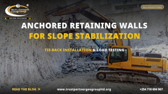
Anchored Retaining Walls for Slope Stabilization: Tie-Back Installation & Load Testing
Ground anchor tie-backs, slope stabilization, shotcrete facing, load testing & corrosion protection for hillside roads, basements & deep cuts in Nairobi, Kiambu & across Kenya
Table of Contents
- 1. What Are Anchored Retaining Walls and Tie-Backs?
- 2. When to Specify Ground Anchors vs. Gravity or Cantilever Walls
- 3. Types of Ground Anchors and Tie-Back Systems
- 4. Anchor Design: Bond Length, Free Length and Lock-Off Load
- 5. Drilling and Installation Sequence
- 6. Corrosion Protection and Durability in Kenyan Soils
- 7. Load Testing: Proof Tests, Performance Tests and Acceptance
- 8. Slope Stabilization Applications in Nairobi
- 9. Groundwater and Drainage Behind Anchored Walls
- 10. Equipment for Tie-Back Installation in Kenya
- 11. Noise, Vibration and Urban Constraints
- 12. NEMA, NCA and County Compliance
- 13. Construction Costs and Programme [2026]
- 14. Frequently Asked Questions
- 15. Conclusion
On the steep hillside cuts of Kiambu Road, where red laterite slopes threaten to slide onto the carriageway with every heavy downpour, and in the deep basements of Upper Hill where a wall must stand without internal bracing blocking the construction zone, the anchored retaining wall is the geotechnical solution that turns impossible slopes into stable ground. A tie-back anchor is not merely a bolt in the ground - it is a pre-stressed tendon drilled deep into stable volcanic tuff or basalt, grouted into place, tensioned against a bearing plate, and tested to prove it can hold. This guide covers the full ground anchor retaining wall Nairobi sequence: anchor types, bond and free length design, drilling and grouting, corrosion protection, load testing protocols, slope stabilization applications, and 2026 costs for tie back wall installation across Kenya.
Trust Partners Geo-Group Ltd - Engineering Team
NCA-registered excavation & civil engineering contractor with 15+ years of slope stabilization, ground anchor installation, tie-back load testing and anchored retaining wall experience across East Africa. Reviewed by registered geotechnical engineers.
1. What Are Anchored Retaining Walls and Tie-Backs?
An anchored retaining wall is a retaining structure that resists lateral earth pressure not by its own mass (like a gravity wall) or by cantilever action (like a sheet pile wall), but by transferring the load into the ground behind the wall through tension elements called ground anchors or tie-backs. The system comprises three elements:
- The wall face: a structural element that distributes earth pressure to the anchors. This may be a cast-in-situ concrete wall, precast panels, soldier piles with lagging, or a shotcrete face with welded wire mesh;
- The anchor tendon: a high-strength steel bar or bundle of strands that spans from the wall face into stable ground behind the potential failure plane;
- The anchor head: a bearing plate, wedge grip or nut assembly at the wall face that transfers the tendon force into the wall structure.
The tendon is installed in a drilled hole, grouted into the stable stratum over a defined bond length, and left unbonded over a free length that allows the tendon to stretch under load. After grout curing, the anchor is tensioned (locked off) against the wall face to a specified percentage of its proof load, typically 70-80%. This pre-stressing actively pulls the wall into the retained soil, mobilizing soil strength and reducing wall deflection.
In Kenya, anchored walls are used for:
- Steep hillside road cuts where gravity walls would require excessive base width and property acquisition;
- Deep basement walls where internal struts would obstruct construction equipment and programme;
- Stabilization of existing failing slopes in residential areas (Kitisuru, Karen, Ngong);
- Temporary excavation support where the anchor can be de-stressed and removed after construction;
- Stabilization of cut slopes alongside railways, pipelines and power corridors where space is minimal.
2. When to Specify Ground Anchors vs. Gravity or Cantilever Walls
The choice between anchored walls and other retaining systems depends on height, soil conditions, space, groundwater, and cost. Ground anchors are not always the answer - but when they are, they solve problems that other walls cannot.
| Condition | Anchored Wall | Gravity Wall | Cantilever Sheet Pile |
|---|---|---|---|
| Wall height > 6m | Economical | Uneconomical - massive base | Possible with heavy section |
| Limited space behind wall | Excellent - anchors go deep, not wide | Poor - needs wide base | Good - vertical wall |
| Excellent - anchors intercept failure plane | Poor - surcharge overloads base | Fair - needs deep embedment | |
| Need for open excavation | Excellent - no internal bracing | N/A | Poor - needs struts or rakers |
| Rock or dense soil behind | Excellent - high bond strength | Fair | Fair |
| Soft clay or loose fill behind | Poor - low bond, creep risk | Fair | Poor |
| Groundwater behind wall | Requires drainage - not a cut-off | Requires drainage | Good cut-off if continuous |
| Cost for 8m height | Medium | High | Medium-High |
Selection guidance for Nairobi:
- Kiambu and Rift Valley hillside road cuts: anchored walls are preferred because the stable basalt or tuff behind the cut provides excellent bond, and there is no space for a gravity wall base on the road edge;
- Upper Hill deep basements with complex layouts: ground anchors from the basement wall into the surrounding soil eliminate the maze of internal struts that would obstruct tower crane bases and concrete pumping;
- Kitisuru and Karen residential slopes: soil nail or anchor walls stabilize existing slopes without the visual bulk of concrete gravity walls;
- Sites with loose fill or soft clay behind the wall: anchors are generally unsuitable due to low bond strength and creep. Consider soil improvement, grouting, or alternative wall types;
- Temporary excavations where anchors must be removed: bar anchors can be de-stressed and extracted; strand anchors are typically cut and abandoned (though this has environmental implications NEMA may query).
3. Types of Ground Anchors and Tie-Back Systems
Ground anchors are classified by tendon type, installation method, load capacity, and design life. The correct specification depends on the project requirements.
Bar Anchors vs. Strand Anchors
| Type | Tendon | Typical Load | Typical Length | Best For |
|---|---|---|---|---|
| Bar anchor | Single threaded steel bar (25-50mm diameter) | 100-500 kN | 8-20m | Temporary works, medium loads, easy de-stressing |
| Strand anchor | Bundle of 3-12 prestressing strands (12.7 or 15.7mm) | 500-3000 kN | 15-40m | Permanent works, high loads, deep stable stratum |
| Self-drilling anchor | Hollow bar with continuous thread | 100-400 kN | 5-15m | Unstable ground, simultaneous drill and grout |
| Soil nail | Single bar (20-32mm), passive | 30-100 kN | 5-12m | Temporary slope stabilization, close spacing |
Bar anchors are the workhorse of Kenyan construction: simple to install, easy to tension with a standard hydraulic jack, and fully de-stressable for temporary works. Strand anchors are specified for permanent walls and high loads where the stable stratum is deep. Self-drilling hollow bar anchors are increasingly used in Nairobi's loose volcanic soils where hole collapse during drilling is a risk - the hollow bar acts as both drill rod and tendon, with grout pumped through the bar during withdrawal.
Temporary vs. Permanent Anchors
Temporary anchors have a design life of up to 2 years and require only single corrosion protection (grout cover). Permanent anchors have a design life of 50-100 years and require double corrosion protection (DCP) with an inner sheath and corrosion-inhibiting compound. In Kenya, county building inspectors and NEMA increasingly require DCP for all permanent anchored walls, particularly where anchors pass through groundwater zones.
Active vs. Passive Anchors
Active (post-tensioned) anchors are tensioned after grouting to a specified lock-off load, pre-stressing the wall. Passive anchors are not tensioned; they mobilize resistance only as the wall moves. Tie-backs are active anchors. Soil nails are passive anchors. Active anchors control deflection; passive anchors are simpler but allow more movement before resisting.
4. Anchor Design: Bond Length, Free Length and Lock-Off Load
The geotechnical engineer designs each anchor based on the wall height, soil profile, groundwater, and surcharge. The design output is a drawing showing anchor spacing, inclination, bond length, free length, and lock-off load for every row.
Bond Length
The bond length is the portion of the anchor embedded in stable ground where grout transfers load to the surrounding soil or rock. It is calculated as:
Bond Length = (Design Load x Safety Factor) / (Unit Bond Strength x Hole Perimeter)
Typical unit bond strengths in Nairobi soils:
- Weathered volcanic tuff: 100-150 kPa;
- Dense Nairobi laterite: 150-250 kPa;
- Fresh to moderately weathered basalt: 500-1000 kPa;
- Soft clay or loose fill: 30-60 kPa (generally unsuitable for anchors).
For a 300 kN design load in weathered tuff with a safety factor of 2.0 and 150mm hole diameter, the required bond length is approximately 8.5 metres. In practice, bond lengths for Nairobi hillside projects range from 5 metres (rock) to 12 metres (weathered soil).
Free Length
The free length is the unbonded section between the wall face and the start of the bond zone. It must extend beyond the potential failure plane of the retained soil mass - typically 1.5-2.0 metres beyond the critical slip surface. Free lengths in Nairobi range from 5 metres for shallow walls to 15 metres for deep basement anchors that must reach stable basalt below weathered tuff. The free length is protected by a smooth HDPE sheath that prevents grout bonding and allows the tendon to stretch elastically under load.
Lock-Off Load
The lock-off load is the tension maintained in the anchor after the jack is released. It is typically 70-80% of the proof test load, which is itself 1.25-1.5 times the design load. For a 300 kN design load, the proof test load is 375-450 kN, and the lock-off load is 260-360 kN. Lock-off at too low a percentage allows wall movement before the anchor engages; lock-off at too high a percentage risks overstressing the tendon or causing creep in the bond zone.
Anchor Spacing and Inclination
Typical spacing is 1.5-3.0 metres horizontally and 1.5-2.5 metres vertically between rows. Inclination below horizontal ranges from 10 degrees (near-horizontal for basement walls) to 45 degrees (steep downward for slope stabilization). Steeper angles reach stable ground faster but reduce the horizontal component of anchor force. The optimum angle balances drilling depth with horizontal resistance.
5. Drilling and Installation Sequence
Anchor installation is a precision operation. A failed anchor is not discovered until load testing - by which time the wall may already be partially constructed. Discipline in drilling, grouting, and curing is essential.
Step 1: Set-Out and Drilling
Anchor positions are marked on the wall face at design spacing and inclination. A track-mounted hydraulic drill rig drills holes of 100-200mm diameter through the wall face (if existing) or from the exposed slope face. In Nairobi's volcanic soils, rotary percussion drilling is standard; in rock, down-the-hole hammers are used. Where loose soils threaten hole collapse, temporary steel casing is advanced with the drill bit (duplex drilling) and withdrawn during grouting.
Step 2: Hole Cleaning and Inspection
The drilled hole is flushed with air and water to remove drill cuttings and loose material. A borehole camera or light-and-mirror inspection verifies hole depth, alignment, and groundwater ingress. The hole depth must exceed the design by at least 300mm to accommodate grout loss at the toe.
Step 3: Tendon Insertion
The tendon (bar or strand) is assembled with centralizers that keep it centred in the hole, ensuring uniform grout cover. For strand anchors, the bond length is fitted with spacers and the free length is sheathed in HDPE. The tendon is lowered carefully to avoid damaging the sheath or displacing centralizers.
Step 4: Grouting
Grout is mixed in a high-shear colloidal mixer to a water-cement ratio of 0.4-0.5, with additives for bleed control and expansion. Grout is pumped from the bottom of the hole upward (tremie method) to displace water and air. Grout pressure at the collar is typically 2-5 bar for soil anchors and up to 10 bar for rock anchors with post-grouting. The volume injected is recorded and compared to theoretical hole volume; excess grout indicates fissures or voids, while deficient volume indicates blockage.
Step 5: Curing
Grout must cure before testing. For ordinary Portland cement grout at 20-25 degrees Celsius (standard Nairobi conditions), minimum curing is 3 days for bar anchors and 7 days for strand anchors. Accelerated curing with additives can reduce this to 24-48 hours for temporary anchors on fast-track programmes.
Critical rule: never test before adequate curing
Testing an anchor before grout has achieved sufficient strength transfers load to a weak bond zone, causing premature failure that may not represent the anchor's true capacity. On a Nairobi project where a contractor tested strand anchors after 2 days to save programme time, 40% of anchors failed proof test and had to be re-drilled. The cost of re-drilling exceeded the savings from the accelerated programme. The specification must state minimum curing times and prohibit early testing without engineer approval.
6. Corrosion Protection and Durability in Kenyan Soils
Kenya's lateritic soils are naturally acidic (pH 4.5-6.5 in some zones) and can be aggressive to unprotected steel. Groundwater in volcanic areas may contain sulfates and chlorides that accelerate corrosion. For permanent anchored walls, corrosion protection is not optional - it is a structural requirement.
Double Corrosion Protection (DCP)
DCP for strand anchors consists of: an inner corrugated HDPE sheath encapsulating the entire tendon, filled with corrosion-inhibiting wax or grease; the primary grout column surrounding the inner sheath in the bond zone; and an outer grout column or second sheath protecting the free length. The anchor head is protected by a steel cover cap filled with grease and sealed with gaskets. DCP adds 25-35% to tendon cost but provides a 100-year design life.
Single Corrosion Protection
For temporary anchors (design life under 2 years), single protection is acceptable: the tendon is protected by the grout column alone, with a minimum grout cover of 20mm. Bar anchors may be hot-dip galvanized (80-100 micron zinc layer) or epoxy-coated for additional protection in moderately aggressive soils.
Kenyan Soil Considerations
In Nairobi's red laterite, the high iron oxide content indicates acidity that can attack unprotected steel. In areas with seasonal groundwater fluctuation (Karen, Lavington, parts of Westlands), the wet-dry cycle accelerates corrosion. For permanent walls in these areas, DCP is mandatory. NEMA may require a geotechnical baseline study including soil pH, resistivity, and groundwater chemistry before approving permanent anchor installations.
7. Load Testing: Proof Tests, Performance Tests and Acceptance
Load testing is the quality control that proves the anchor will perform as designed. Kenyan practice follows BS 8081 and EN 1537, adapted for local soil conditions. Three test categories are required.
Proof Tests (Every Anchor)
Every production anchor is proof tested. The anchor is loaded in increments (typically 25%, 50%, 75%, 100%, 125% of design load) to a maximum of 1.25-1.5 times design load. At each increment, displacement is recorded. The maximum load is held for 10 minutes, with displacement readings at 1, 2, 5 and 10 minutes. The anchor passes if the creep (displacement between readings) is less than 2mm in the final hold period. Failed anchors are either re-tested after re-grouting or replaced.
Performance Tests (5-10% of Anchors)
Performance tests are carried out on a representative sample (minimum 3 anchors) with cyclic loading: load to 50%, unload to lock-off, load to 100%, unload, load to 125%, unload, load to 150%, hold. The test measures elastic displacement (recoverable) and residual displacement (permanent). The elastic displacement should align with theoretical tendon elongation; excessive residual displacement indicates bond zone degradation or free length grouting. Performance tests provide the data to confirm the design bond length and adjust if necessary.
Creep Tests (Critical Permanent Anchors)
For anchors in soils with creep potential (clay, weathered tuff with clay seams), an extended creep test holds the proof load for 60 minutes with readings every 15 minutes. The anchor passes if creep rate is less than 2mm in the final 15 minutes. Creep tests are essential in Nairobi's volcanic soils where smectite clay layers can cause time-dependent deformation.
Lock-Off and Documentation
After successful testing, the anchor is locked off at 70-80% of proof load using a hollow ram jack and shim plates. The lock-off load, displacement, and shim thickness are recorded. A steel protective cap is fitted over the anchor head. All test records, load-displacement curves, and as-built anchor coordinates are compiled in a handover package for the county building inspector and client.
| Test Type | Frequency | Max Load | Hold Time | Pass Criteria |
|---|---|---|---|---|
| Proof test | Every anchor | 1.25-1.5 x design | 10 minutes | <2mm creep in final hold |
| Performance test | 5-10% (min 3) | 1.5 x design | Cyclic | Elastic displacement matches theory |
| Creep test | Critical anchors | 1.25 x design | 60 minutes | <2mm in final 15 minutes |
8. Slope Stabilization Applications in Nairobi
Nairobi's topography - a highland plateau dissected by river valleys and volcanic ridges - creates natural and cut slopes that require stabilization. The city's rapid expansion into hillside areas (Kitisuru, Karen, Ngong, Kiambu) has increased demand for anchored slope solutions.
Typical Nairobi Slope Conditions
Nairobi slopes typically comprise: topsoil and organic layer (0.3-1.0m); red laterite or volcanic ash (1.0-5.0m); weathered tuff or agglomerate (5.0-15.0m); and fresh or fractured basalt below. The critical failure surface often follows the weathered tuff-fresh basalt interface, where groundwater accumulates and reduces shear strength. Anchors for slope stabilization must penetrate through the weathered zone and achieve bond in the fresh basalt or dense tuff.
Road Cut Stabilization
Kiambu Road, Ngong Road, and the Rift Valley escarpment highways feature steep cut slopes where road widening has removed the natural toe support. Anchored walls with shotcrete facing stabilize these cuts without the land-take required for gravity walls. A typical Kiambu Road project uses 12-15 metre long bar anchors at 2.0m spacing, with 100mm shotcrete facing and weep holes, to support a 45-degree cut slope.
Residential Hillside Protection
In Kitisuru and Loresho, residential developments on steep plots require cut-and-fill earthworks that destabilize natural slopes. Anchored walls with architectural concrete facing or shotcrete with pigment provide structural support without the visual impact of gabions or mass concrete. Where slope movement is already occurring, active anchors can halt displacement and allow the construction of houses above the stabilized zone.
Basement Wall Anchoring
In Upper Hill and Kilimani, deep basement walls are increasingly anchored rather than strutted. Ground anchors drilled from the basement wall into the surrounding soil eliminate internal bracing, freeing the excavation for tower crane bases, concrete pumps, and construction traffic. Basement anchors are typically bar anchors of 10-15m length, installed from the inside face of a soldier pile or diaphragm wall, and de-stressed after the basement slab is cast.
9. Groundwater and Drainage Behind Anchored Walls
Ground anchors do not stop water. The drilled holes for anchors can even act as conduits for groundwater if not properly sealed. Drainage design is integral to anchored wall performance.
Water Ingress Risks
- Anchor holes as conduits: if the annulus around the anchor tendon is not fully grouted, water can flow down the hole and emerge at the wall face, eroding grout and corroding the tendon;
- Hydrostatic pressure: water accumulating behind the wall face creates hydrostatic pressure that adds to earth pressure. An anchored wall designed for soil pressure alone can fail if water pressure is not relieved;
- Seasonal groundwater rise: Nairobi's long rains (March-May) can raise groundwater levels by 2-3 metres in hillside areas, increasing pore water pressure behind walls designed for dry-season conditions.
Drainage Measures
| Drainage Element | Application | Typical Cost |
|---|---|---|
| Weep holes through wall face | Relieve hydrostatic pressure at wall | KES 500-1,000 per hole |
| Geotextile filter behind shotcrete | Prevent soil loss through weep holes | KES 150-300/m2 |
| Granular drainage blanket (300mm) | Collect and channel groundwater | KES 800-1,500/m2 |
| Perforated subsoil drain pipe | Collect water from drainage blanket | KES 400-700/m |
| Grout seal around anchor head | Prevent water ingress down anchor hole | Included in anchor cost |
In Nairobi's highland areas with deep groundwater, drainage may be minimal. In low-lying or hillside spring zones, a comprehensive drainage system with weep holes, geotextile, and subsoil drains is essential. Discharge must pass through a silt trap before release to stormwater systems, per NEMA and WRA requirements.
10. Equipment for Tie-Back Installation in Kenya
Anchor installation requires specialist geotechnical drilling equipment that is distinct from standard piling or water-well rigs:
| Equipment | Role | Typical Specification |
|---|---|---|
| Track-mounted drill rig | Drilling anchor holes | Rotary percussion, 150-300mm diameter, 30-50m depth |
| Duplex drilling system | Drilling in loose/collapsing ground | Outer casing + inner drill string, simultaneous advance |
| Colloidal grout mixer | High-quality cement grout | 200-500 litre capacity, high-shear mixing |
| High-pressure grout pump | Injecting grout into holes | 50-100 bar, 20-50 L/min |
| Hollow ram hydraulic jack | Load testing and lock-off | 50-200 tonne, with calibrated gauge and dial gauge |
| Strand jack (for strand anchors) | Tensioning multi-strand tendons | 100-500 tonne, mono-strand or multi-strand |
| Shotcrete pump and nozzle | Wall facing application | Wet-mix, 5-10 m3/hr, robotic arm |
| Excavator with breaker | Slope trimming and face preparation | 20-30 tonne |
Site access is a significant planning factor for hillside projects. Track-mounted drill rigs require a stable platform of 4-6 metres width. On steep slopes, benches must be cut to accommodate the rig, which adds to earthworks volume and programme. In confined urban basements, smaller skid-mounted drills or excavator-mounted drill attachments are used, though they are slower and limited to shorter anchors.
11. Noise, Vibration and Urban Constraints
Anchor installation in urban Nairobi operates under the same noise and vibration constraints as other geotechnical works, with additional considerations for hillside residential areas:
- Drilling noise: rotary percussion drilling produces 85-100 dB at the rig. In residential Kitisuru or Karen, this requires acoustic enclosures around the drill head or restricted hours (07:30-17:30 weekdays, 08:00-13:00 Saturdays);
- Vibration: percussion drilling in rock generates 5-15 mm/s PPV at the rig, which attenuates with distance. At 10 metres from the rig, vibration is typically 2-5 mm/s - acceptable for most residential buildings but requiring monitoring near sensitive structures;
- Dust: dry drilling in volcanic soils produces fine silica dust that is hazardous to operators and neighbours. Wet drilling (water flush) is mandatory in urban areas and suppresses dust effectively;
- Traffic: drill rigs, grout mixers, and shotcrete pumps require road access and parking. On narrow hillside roads (Kiambu, Ngong), traffic management plans and KeNHA/county approval are required;
- Adjacent property: anchors drilled from one property into the subsurface may pass beneath neighbouring land. While the anchor itself is at depth, the drilling operation and potential grout loss at the surface can cause disputes. Party wall agreements and geotechnical easements should be secured before drilling begins.
NEMA may require an Environmental Management Plan (EMP) for hillside anchor projects involving vegetation clearance, significant earthworks, or operation within 100 metres of watercourses. The EMP covers noise, dust, erosion control, and drainage discharge.
12. NEMA, NCA and County Compliance
Anchored retaining wall projects in Kenya trigger multiple regulatory layers, with additional geotechnical documentation requirements:
| Requirement | Authority | What It Covers |
|---|---|---|
| Building plan approval | County government | Structural drawings, anchor layout, wall facing design |
| NEMA approval | NEMA | Hillside vegetation, earthworks, drainage discharge, EMP |
| NCA registration | National Construction Authority | Contractor registration, specialist anchor installer |
| Geotechnical design certification | Registered geotechnical engineer | Anchor design, bond length, test criteria |
| Load test records | County building inspector | Proof and performance test results for every anchor |
| Traffic / road reserve | KeNHA / KURA / County | Rig positioning, road space, traffic control |
| Water discharge permit | Water Resources Authority | Drainage discharge to stormwater or natural channels |
| Adjacent land consent | Civil / County | Drilling easements, monitoring access, party walls |
The anchor design must be certified by a registered geotechnical or structural engineer with specific experience in ground anchor systems. County building inspectors in Nairobi and Kiambu are increasingly requiring submission of load test records before signing off on the temporary works certificate. For permanent anchored walls, a 10-year maintenance and inspection plan is standard, with anchor head inspections every 2 years and re-tensioning if lock-off loss exceeds 10%.
13. Construction Costs and Programme [2026]
Indicative costs for anchored retaining wall and tie-back installation in Kenya:
| Item | 2026 Rate | Notes |
|---|---|---|
| Drilling and grouting (soil) | KES 3,000-6,000/m | Per metre of anchor hole, including flush |
| Drilling and grouting (rock) | KES 4,000-8,000/m | Harder drilling, slower production |
| Bar anchor tendon supply | KES 800-1,500/m | 25-40mm threaded bar, temporary |
| Strand anchor tendon supply | KES 1,500-3,000/m | 3-12 strand bundle, permanent |
| Double corrosion protection (DCP) | Add 25-35% | Inner sheath, wax, caps |
| Anchor head and bearing plate | KES 8,000-20,000 each | Bar head or strand wedge plate |
| Proof load testing | KES 15,000-30,000 each | Every anchor |
| Performance load testing | KES 40,000-80,000 each | 5-10% of anchors |
| Shotcrete wall facing with mesh | KES 2,500-4,000/m2 | 75-100mm thickness |
| Concrete wall facing (precast) | KES 3,500-6,000/m2 | Includes installation |
| Soldier pile wall with anchors | KES 4,000-8,000/m2 | Piles + lagging + anchors |
| Drainage system (weep holes + pipe) | KES 1,000-2,000/m2 | Of wall face area |
| Mobilization / demobilization | KES 150,000-400,000 | Drill rig, grout plant, transport |
All-in project estimates:
- 6m high slope wall, 20 bar anchors, shotcrete facing: KES 2.5-4.0 million;
- 10m high slope wall, 30 strand anchors, shotcrete facing: KES 5.5-9.0 million;
- 8m deep basement wall, soldier piles + steel lagging + bar anchors: KES 4.5-7.5 million;
- 15m high road cut, 50 strand anchors, precast facing: KES 12-18 million.
Programme: mobilization 2-3 days; slope trimming and face preparation 3-5 days; drilling and grouting 1-2 weeks depending on anchor count and depth; grout curing 3-7 days; load testing 3-5 days; wall facing 1-2 weeks; drainage and finishing 2-3 days. A typical 30-anchor hillside project takes 4-6 weeks from mobilization to completion.
Pro tip: test early, test often
On anchored wall projects, the first three anchors should be sacrificial investigation anchors tested to failure. These establish the actual bond strength in the ground and allow the engineer to confirm or adjust the design bond length before drilling the remaining anchors. Trust Partners Geo-Group Ltd installs investigation anchors at no additional programme cost on projects over 20 anchors, saving clients from the expense of over-designed bond lengths or the risk of under-designed anchors.
14. Frequently Asked Questions: Anchored Retaining Walls in Kenya
What is an anchored retaining wall and how does it work?
An anchored retaining wall is a retaining structure stabilized by ground anchors (tie-backs) drilled diagonally from the wall face into stable soil or rock behind the wall. Each anchor consists of a tendon (steel bar or strand bundle) grouted into a drilled hole, with an anchor head and bearing plate at the wall face. The tendon transfers tensile force from the wall into the stable ground behind the potential failure plane, allowing the wall to resist lateral earth pressure without relying on mass or cantilever action. In Kenya, anchored walls are used for steep hillside road cuts in Kiambu, deep basement walls in Upper Hill where internal bracing is impractical, and slope stabilization along the Ngong and Rift Valley escarpments where gravity walls would require excessive base width.
What is the difference between a tie-back anchor and a soil nail?
A tie-back anchor is an active structural element that is post-tensioned after installation, applying a pre-stressing force to the wall face. It has a defined bond length in stable ground and a free length that allows the tendon to stretch under load. Tie-backs are typically installed at wider spacing (1.5-3.0 metres) and carry high loads (100-3000 kN per anchor). A soil nail is a passive reinforcement element that is not post-tensioned; it relies on soil deformation to mobilize resistance. Soil nails are installed at close spacing (1.0-1.5 metres) in a grid pattern and work collectively with a shotcrete facing to stabilize the soil mass. In Nairobi, tie-backs are used for permanent structural walls and deep cuts, while soil nails are used for temporary slope stabilization and less critical hillside applications.
How deep are ground anchor bond lengths in Nairobi soils?
Ground anchor bond lengths in Nairobi depend on the soil or rock type in the anchoring zone. In weathered volcanic tuff, bond lengths of 6-10 metres are typical to achieve design loads of 200-500 kN. In dense Nairobi laterite, bond lengths of 5-8 metres are usually sufficient. In fresh or moderately weathered basalt, bond lengths can be reduced to 3-5 metres because rock-grout bond strength is significantly higher than soil-grout bond. The free length (unbonded section) extends from the wall face to the start of the bond zone, typically 5-12 metres depending on the depth of the stable stratum. The geotechnical engineer calculates the required bond length based on grout-soil or grout-rock bond strength, anchor design load, and a safety factor of 2.0-3.0.
What does tie-back anchor installation cost in Kenya in 2026?
2026 indicative costs for tie-back anchor installation in Kenya: drilling and grouting KES 3,000-6,000 per metre of anchor; bar anchor tendon supply KES 800-1,500 per metre; strand anchor tendon supply KES 1,500-3,000 per metre; anchor head and bearing plate KES 8,000-20,000 per anchor; proof load testing KES 15,000-30,000 per anchor; performance load testing KES 40,000-80,000 per anchor; double corrosion protection (DCP) add 25-35% to tendon cost; wall facing (shotcrete with mesh) KES 2,500-4,000 per m2. A typical anchored retaining wall with 20 anchors of 15m length each, shotcrete facing, and full testing costs KES 2.5-4.5 million for the anchor system plus KES 1.5-3.0 million for the wall facing, excluding excavation and drainage. Soil nail walls are cheaper at KES 1,500-2,500 per m2 of facing but carry lower loads.
What load tests are required for ground anchors in Kenya?
Kenyan practice follows BS 8081 and EN 1537 for ground anchor testing. Three test types are required: Proof tests are carried out on every production anchor to 1.25-1.5 times the design load, held for 10 minutes with creep displacement measured. The anchor passes if creep is less than 2mm in the final hold period. Performance tests are carried out on 5-10% of anchors (minimum 3) with cyclic loading to 1.5 times design load, measuring elastic and residual deformation to verify bond capacity and tendon performance. Creep tests extend the hold period to 60 minutes at proof load for critical permanent anchors. All test records must be signed by the geotechnical engineer and submitted to the county building inspector. Trust Partners Geo-Group Ltd provides in-house testing with calibrated hollow ram jacks and dial gauges, with third-party verification available.
How is corrosion protection provided for permanent ground anchors in Kenya?
Permanent ground anchors in Kenya require double corrosion protection (DCP) because lateritic soils can be acidic and groundwater chemistry varies. DCP consists of: an inner corrugated HDPE sheath encapsulating the tendon, filled with corrosion-inhibiting grease or wax; a primary grout column surrounding the inner sheath in the bond zone; and an outer grout column or corrugated sheath protecting the free length. The anchor head is protected by a steel cover cap filled with grease. For bar anchors, hot-dip galvanizing or epoxy coating provides additional protection. Single corrosion protection (grout cover only) is acceptable for temporary anchors with a design life under 2 years. NEMA and county building codes require corrosion protection details to be shown on the structural drawings for all permanent anchored walls.
What equipment is used for tie-back anchor installation in Kenya?
Tie-back anchor installation in Kenya uses: track-mounted hydraulic drill rigs with rotary percussion heads (capable of drilling 100-200mm diameter holes to 30m depth in soil and rock); duplex drilling systems (outer casing with inner drill string) for unstable ground; high-pressure grout pumps (50-100 bar) with colloidal mixers for cement grout; hollow ram hydraulic jacks (50-200 tonne capacity) with calibrated pressure gauges and dial gauges for load testing; strand cutters and swaging equipment for anchor head assembly; and shotcrete pumps with robotic nozzles for wall facing application. In confined urban sites, smaller excavator-mounted drill attachments are used for anchors under 15m length. The equipment is specialized and requires operators trained in geotechnical drilling and anchor installation protocols.
Do anchored retaining walls need building approval in Kenya?
Yes. Anchored retaining walls and slope stabilization works require county building plan approval including geotechnical investigation reports, anchor design calculations, and structural drawings for the wall facing. NEMA approval is required for hillside projects involving vegetation clearance, significant earthworks, or operation within 100 metres of watercourses. NCA-registered contractors must execute the works, and a registered geotechnical or structural engineer must design and certify the anchor system. For walls over 4 metres high or supporting roads and buildings, the county requires proof and performance test records, a method statement for drilling and grouting, and third-party monitoring of adjacent structures. KeNHA or KURA approval is needed for road reserve works. Insurance, public liability coverage, and a 10-year maintenance plan for permanent anchors are standard requirements.
15. Conclusion: Tension, Testing and Trust
An anchored retaining wall is a geotechnical contract between the structure and the ground. The wall face holds the soil; the anchor tendon reaches past the failure plane into stable ground; the grout bond transfers the load; and the test jack proves it will hold. Every element must perform, because the anchor is hidden forever after lock-off - there is no visual inspection of the bond zone, no easy replacement of a failed tendon. The design must be conservative, the drilling must be clean, the grout must be sound, and the testing must be rigorous.
In Nairobi's volcanic terrain, the ground anchor is often the only solution that can stabilize a steep hillside cut or free a deep basement from the obstruction of internal struts. But it demands expertise: the geotechnical engineer who knows the difference between weathered tuff and fresh basalt; the driller who keeps the hole straight and the sheath intact; the tester who reads the load-displacement curve and knows when creep is acceptable and when it signals failure.
Trust Partners Geo-Group Ltd delivers the full anchored wall package across Kenya: geotechnical investigation and anchor design, drilling and grouting with duplex systems for unstable ground, bar and strand anchor supply with double corrosion protection, load testing with calibrated equipment and certified records, shotcrete and concrete wall facing, drainage systems, and long-term monitoring. We work with your geotechnical engineer's design, manage NEMA and county compliance for hillside projects, and deliver safe, tested, documented anchor installations - on unit-rate or lump-sum contracts, with NCA-registered crews and specialist drilling equipment.
Ground Anchor & Tie-Back Installation
Ground anchor tie-backs, slope stabilization, load testing, shotcrete facing, and anchored retaining wall construction for hillside and road projects across Nairobi and Kenya.
Free lead magnet: ask for our Ground Anchor Installation & Testing Checklist (PDF) - anchor hold points, grout records, load test protocols and corrosion protection standards your geotechnical engineer will require.
Related Resources
Soldier Pile and Lagging Wall Systems: Excavation Support for Deep Cuts in Urban Nairobi
The previous blog in our retaining wall series - discontinuous soldier pile shoring with timber and steel lagging for boulder-filled ground.
READ MORESheet Pile Wall Installation for Basement Excavation in Nairobi: Driven vs. Vibratory Methods
Continuous interlocking steel sheet piles for deep basements with groundwater control.
READ MOREReinforced Earth Retaining Walls for Road Projects: MSE Wall Excavation & Installation
Mechanically stabilized earth walls for highways and road projects across Kenya.
READ MORESlope Excavation and Stabilization for Hillside Construction in Nairobi & Kiambu
Cut slopes, benching and stabilization techniques for hillside building and road projects.
READ MOREGravity Retaining Wall Construction in Kenya: Excavation, Footing Design & Drainage
Mass walls, stone masonry and gabion earthworks for hillside and boundary applications.
READ MOREEarthworks QA/QC: Compaction Testing & Density Control
The layer-by-layer testing regime for excavation backfill and shoring earthworks.
READ MORETRUST PARTNERS GEO-GROUP LTD | YOUR VISION, OUR EXCAVATION
WEBSITE: WWW.TRUSTPARTNERGEOGROUPLTD.ORG | EMAIL: INFO@TRUSTPARTNERGEOGROUPLTD.ORG | PHONE: +254 718 68 69 67
FOLLOW US: FACEBOOK | TIKTOK | INSTAGRAM | YOUTUBE | LINKEDIN
© 2026 TRUST PARTNERS GEO-GROUP LTD. ALL RIGHTS RESERVED.
Anchored Retaining Walls for Slope Stabilization: Tie-Back Installation & Load Testing
Ground anchor tie-backs, slope stabilization, shotcrete facing, load testing & corrosion protection for hillside roads, basements & deep cuts in Nairobi, Kiambu & across Kenya
Table of Contents
- 1. What Are Anchored Retaining Walls and Tie-Backs?
- 2. When to Specify Ground Anchors vs. Gravity or Cantilever Walls
- 3. Types of Ground Anchors and Tie-Back Systems
- 4. Anchor Design: Bond Length, Free Length and Lock-Off Load
- 5. Drilling and Installation Sequence
- 6. Corrosion Protection and Durability in Kenyan Soils
- 7. Load Testing: Proof Tests, Performance Tests and Acceptance
- 8. Slope Stabilization Applications in Nairobi
- 9. Groundwater and Drainage Behind Anchored Walls
- 10. Equipment for Tie-Back Installation in Kenya
- 11. Noise, Vibration and Urban Constraints
- 12. NEMA, NCA and County Compliance
- 13. Construction Costs and Programme [2026]
- 14. Frequently Asked Questions
- 15. Conclusion
On the steep hillside cuts of Kiambu Road, where red laterite slopes threaten to slide onto the carriageway with every heavy downpour, and in the deep basements of Upper Hill where a wall must stand without internal bracing blocking the construction zone, the anchored retaining wall is the geotechnical solution that turns impossible slopes into stable ground. A tie-back anchor is not merely a bolt in the ground - it is a pre-stressed tendon drilled deep into stable volcanic tuff or basalt, grouted into place, tensioned against a bearing plate, and tested to prove it can hold. This guide covers the full ground anchor retaining wall Nairobi sequence: anchor types, bond and free length design, drilling and grouting, corrosion protection, load testing protocols, slope stabilization applications, and 2026 costs for tie back wall installation across Kenya.
Trust Partners Geo-Group Ltd - Engineering Team
NCA-registered excavation & civil engineering contractor with 15+ years of slope stabilization, ground anchor installation, tie-back load testing and anchored retaining wall experience across East Africa. Reviewed by registered geotechnical engineers.
1. What Are Anchored Retaining Walls and Tie-Backs?
An anchored retaining wall is a retaining structure that resists lateral earth pressure not by its own mass (like a gravity wall) or by cantilever action (like a sheet pile wall), but by transferring the load into the ground behind the wall through tension elements called ground anchors or tie-backs. The system comprises three elements:
- The wall face: a structural element that distributes earth pressure to the anchors. This may be a cast-in-situ concrete wall, precast panels, soldier piles with lagging, or a shotcrete face with welded wire mesh;
- The anchor tendon: a high-strength steel bar or bundle of strands that spans from the wall face into stable ground behind the potential failure plane;
- The anchor head: a bearing plate, wedge grip or nut assembly at the wall face that transfers the tendon force into the wall structure.
The tendon is installed in a drilled hole, grouted into the stable stratum over a defined bond length, and left unbonded over a free length that allows the tendon to stretch under load. After grout curing, the anchor is tensioned (locked off) against the wall face to a specified percentage of its proof load, typically 70-80%. This pre-stressing actively pulls the wall into the retained soil, mobilizing soil strength and reducing wall deflection.
In Kenya, anchored walls are used for:
- Steep hillside road cuts where gravity walls would require excessive base width and property acquisition;
- Deep basement walls where internal struts would obstruct construction equipment and programme;
- Stabilization of existing failing slopes in residential areas (Kitisuru, Karen, Ngong);
- Temporary excavation support where the anchor can be de-stressed and removed after construction;
- Stabilization of cut slopes alongside railways, pipelines and power corridors where space is minimal.
2. When to Specify Ground Anchors vs. Gravity or Cantilever Walls
The choice between anchored walls and other retaining systems depends on height, soil conditions, space, groundwater, and cost. Ground anchors are not always the answer - but when they are, they solve problems that other walls cannot.
| Condition | Anchored Wall | Gravity Wall | Cantilever Sheet Pile |
|---|---|---|---|
| Wall height > 6m | Economical | Uneconomical - massive base | Possible with heavy section |
| Limited space behind wall | Excellent - anchors go deep, not wide | Poor - needs wide base | Good - vertical wall |
| Excellent - anchors intercept failure plane | Poor - surcharge overloads base | Fair - needs deep embedment | |
| Need for open excavation | Excellent - no internal bracing | N/A | Poor - needs struts or rakers |
| Rock or dense soil behind | Excellent - high bond strength | Fair | Fair |
| Soft clay or loose fill behind | Poor - low bond, creep risk | Fair | Poor |
| Groundwater behind wall | Requires drainage - not a cut-off | Requires drainage | Good cut-off if continuous |
| Cost for 8m height | Medium | High | Medium-High |
Selection guidance for Nairobi:
- Kiambu and Rift Valley hillside road cuts: anchored walls are preferred because the stable basalt or tuff behind the cut provides excellent bond, and there is no space for a gravity wall base on the road edge;
- Upper Hill deep basements with complex layouts: ground anchors from the basement wall into the surrounding soil eliminate the maze of internal struts that would obstruct tower crane bases and concrete pumping;
- Kitisuru and Karen residential slopes: soil nail or anchor walls stabilize existing slopes without the visual bulk of concrete gravity walls;
- Sites with loose fill or soft clay behind the wall: anchors are generally unsuitable due to low bond strength and creep. Consider soil improvement, grouting, or alternative wall types;
- Temporary excavations where anchors must be removed: bar anchors can be de-stressed and extracted; strand anchors are typically cut and abandoned (though this has environmental implications NEMA may query).
3. Types of Ground Anchors and Tie-Back Systems
Ground anchors are classified by tendon type, installation method, load capacity, and design life. The correct specification depends on the project requirements.
Bar Anchors vs. Strand Anchors
| Type | Tendon | Typical Load | Typical Length | Best For |
|---|---|---|---|---|
| Bar anchor | Single threaded steel bar (25-50mm diameter) | 100-500 kN | 8-20m | Temporary works, medium loads, easy de-stressing |
| Strand anchor | Bundle of 3-12 prestressing strands (12.7 or 15.7mm) | 500-3000 kN | 15-40m | Permanent works, high loads, deep stable stratum |
| Self-drilling anchor | Hollow bar with continuous thread | 100-400 kN | 5-15m | Unstable ground, simultaneous drill and grout |
| Soil nail | Single bar (20-32mm), passive | 30-100 kN | 5-12m | Temporary slope stabilization, close spacing |
Bar anchors are the workhorse of Kenyan construction: simple to install, easy to tension with a standard hydraulic jack, and fully de-stressable for temporary works. Strand anchors are specified for permanent walls and high loads where the stable stratum is deep. Self-drilling hollow bar anchors are increasingly used in Nairobi's loose volcanic soils where hole collapse during drilling is a risk - the hollow bar acts as both drill rod and tendon, with grout pumped through the bar during withdrawal.
Temporary vs. Permanent Anchors
Temporary anchors have a design life of up to 2 years and require only single corrosion protection (grout cover). Permanent anchors have a design life of 50-100 years and require double corrosion protection (DCP) with an inner sheath and corrosion-inhibiting compound. In Kenya, county building inspectors and NEMA increasingly require DCP for all permanent anchored walls, particularly where anchors pass through groundwater zones.
Active vs. Passive Anchors
Active (post-tensioned) anchors are tensioned after grouting to a specified lock-off load, pre-stressing the wall. Passive anchors are not tensioned; they mobilize resistance only as the wall moves. Tie-backs are active anchors. Soil nails are passive anchors. Active anchors control deflection; passive anchors are simpler but allow more movement before resisting.
4. Anchor Design: Bond Length, Free Length and Lock-Off Load
The geotechnical engineer designs each anchor based on the wall height, soil profile, groundwater, and surcharge. The design output is a drawing showing anchor spacing, inclination, bond length, free length, and lock-off load for every row.
Bond Length
The bond length is the portion of the anchor embedded in stable ground where grout transfers load to the surrounding soil or rock. It is calculated as:
Bond Length = (Design Load x Safety Factor) / (Unit Bond Strength x Hole Perimeter)
Typical unit bond strengths in Nairobi soils:
- Weathered volcanic tuff: 100-150 kPa;
- Dense Nairobi laterite: 150-250 kPa;
- Fresh to moderately weathered basalt: 500-1000 kPa;
- Soft clay or loose fill: 30-60 kPa (generally unsuitable for anchors).
For a 300 kN design load in weathered tuff with a safety factor of 2.0 and 150mm hole diameter, the required bond length is approximately 8.5 metres. In practice, bond lengths for Nairobi hillside projects range from 5 metres (rock) to 12 metres (weathered soil).
Free Length
The free length is the unbonded section between the wall face and the start of the bond zone. It must extend beyond the potential failure plane of the retained soil mass - typically 1.5-2.0 metres beyond the critical slip surface. Free lengths in Nairobi range from 5 metres for shallow walls to 15 metres for deep basement anchors that must reach stable basalt below weathered tuff. The free length is protected by a smooth HDPE sheath that prevents grout bonding and allows the tendon to stretch elastically under load.
Lock-Off Load
The lock-off load is the tension maintained in the anchor after the jack is released. It is typically 70-80% of the proof test load, which is itself 1.25-1.5 times the design load. For a 300 kN design load, the proof test load is 375-450 kN, and the lock-off load is 260-360 kN. Lock-off at too low a percentage allows wall movement before the anchor engages; lock-off at too high a percentage risks overstressing the tendon or causing creep in the bond zone.
Anchor Spacing and Inclination
Typical spacing is 1.5-3.0 metres horizontally and 1.5-2.5 metres vertically between rows. Inclination below horizontal ranges from 10 degrees (near-horizontal for basement walls) to 45 degrees (steep downward for slope stabilization). Steeper angles reach stable ground faster but reduce the horizontal component of anchor force. The optimum angle balances drilling depth with horizontal resistance.
5. Drilling and Installation Sequence
Anchor installation is a precision operation. A failed anchor is not discovered until load testing - by which time the wall may already be partially constructed. Discipline in drilling, grouting, and curing is essential.
Step 1: Set-Out and Drilling
Anchor positions are marked on the wall face at design spacing and inclination. A track-mounted hydraulic drill rig drills holes of 100-200mm diameter through the wall face (if existing) or from the exposed slope face. In Nairobi's volcanic soils, rotary percussion drilling is standard; in rock, down-the-hole hammers are used. Where loose soils threaten hole collapse, temporary steel casing is advanced with the drill bit (duplex drilling) and withdrawn during grouting.
Step 2: Hole Cleaning and Inspection
The drilled hole is flushed with air and water to remove drill cuttings and loose material. A borehole camera or light-and-mirror inspection verifies hole depth, alignment, and groundwater ingress. The hole depth must exceed the design by at least 300mm to accommodate grout loss at the toe.
Step 3: Tendon Insertion
The tendon (bar or strand) is assembled with centralizers that keep it centred in the hole, ensuring uniform grout cover. For strand anchors, the bond length is fitted with spacers and the free length is sheathed in HDPE. The tendon is lowered carefully to avoid damaging the sheath or displacing centralizers.
Step 4: Grouting
Grout is mixed in a high-shear colloidal mixer to a water-cement ratio of 0.4-0.5, with additives for bleed control and expansion. Grout is pumped from the bottom of the hole upward (tremie method) to displace water and air. Grout pressure at the collar is typically 2-5 bar for soil anchors and up to 10 bar for rock anchors with post-grouting. The volume injected is recorded and compared to theoretical hole volume; excess grout indicates fissures or voids, while deficient volume indicates blockage.
Step 5: Curing
Grout must cure before testing. For ordinary Portland cement grout at 20-25 degrees Celsius (standard Nairobi conditions), minimum curing is 3 days for bar anchors and 7 days for strand anchors. Accelerated curing with additives can reduce this to 24-48 hours for temporary anchors on fast-track programmes.
Critical rule: never test before adequate curing
Testing an anchor before grout has achieved sufficient strength transfers load to a weak bond zone, causing premature failure that may not represent the anchor's true capacity. On a Nairobi project where a contractor tested strand anchors after 2 days to save programme time, 40% of anchors failed proof test and had to be re-drilled. The cost of re-drilling exceeded the savings from the accelerated programme. The specification must state minimum curing times and prohibit early testing without engineer approval.
6. Corrosion Protection and Durability in Kenyan Soils
Kenya's lateritic soils are naturally acidic (pH 4.5-6.5 in some zones) and can be aggressive to unprotected steel. Groundwater in volcanic areas may contain sulfates and chlorides that accelerate corrosion. For permanent anchored walls, corrosion protection is not optional - it is a structural requirement.
Double Corrosion Protection (DCP)
DCP for strand anchors consists of: an inner corrugated HDPE sheath encapsulating the entire tendon, filled with corrosion-inhibiting wax or grease; the primary grout column surrounding the inner sheath in the bond zone; and an outer grout column or second sheath protecting the free length. The anchor head is protected by a steel cover cap filled with grease and sealed with gaskets. DCP adds 25-35% to tendon cost but provides a 100-year design life.
Single Corrosion Protection
For temporary anchors (design life under 2 years), single protection is acceptable: the tendon is protected by the grout column alone, with a minimum grout cover of 20mm. Bar anchors may be hot-dip galvanized (80-100 micron zinc layer) or epoxy-coated for additional protection in moderately aggressive soils.
Kenyan Soil Considerations
In Nairobi's red laterite, the high iron oxide content indicates acidity that can attack unprotected steel. In areas with seasonal groundwater fluctuation (Karen, Lavington, parts of Westlands), the wet-dry cycle accelerates corrosion. For permanent walls in these areas, DCP is mandatory. NEMA may require a geotechnical baseline study including soil pH, resistivity, and groundwater chemistry before approving permanent anchor installations.
7. Load Testing: Proof Tests, Performance Tests and Acceptance
Load testing is the quality control that proves the anchor will perform as designed. Kenyan practice follows BS 8081 and EN 1537, adapted for local soil conditions. Three test categories are required.
Proof Tests (Every Anchor)
Every production anchor is proof tested. The anchor is loaded in increments (typically 25%, 50%, 75%, 100%, 125% of design load) to a maximum of 1.25-1.5 times design load. At each increment, displacement is recorded. The maximum load is held for 10 minutes, with displacement readings at 1, 2, 5 and 10 minutes. The anchor passes if the creep (displacement between readings) is less than 2mm in the final hold period. Failed anchors are either re-tested after re-grouting or replaced.
Performance Tests (5-10% of Anchors)
Performance tests are carried out on a representative sample (minimum 3 anchors) with cyclic loading: load to 50%, unload to lock-off, load to 100%, unload, load to 125%, unload, load to 150%, hold. The test measures elastic displacement (recoverable) and residual displacement (permanent). The elastic displacement should align with theoretical tendon elongation; excessive residual displacement indicates bond zone degradation or free length grouting. Performance tests provide the data to confirm the design bond length and adjust if necessary.
Creep Tests (Critical Permanent Anchors)
For anchors in soils with creep potential (clay, weathered tuff with clay seams), an extended creep test holds the proof load for 60 minutes with readings every 15 minutes. The anchor passes if creep rate is less than 2mm in the final 15 minutes. Creep tests are essential in Nairobi's volcanic soils where smectite clay layers can cause time-dependent deformation.
Lock-Off and Documentation
After successful testing, the anchor is locked off at 70-80% of proof load using a hollow ram jack and shim plates. The lock-off load, displacement, and shim thickness are recorded. A steel protective cap is fitted over the anchor head. All test records, load-displacement curves, and as-built anchor coordinates are compiled in a handover package for the county building inspector and client.
| Test Type | Frequency | Max Load | Hold Time | Pass Criteria |
|---|---|---|---|---|
| Proof test | Every anchor | 1.25-1.5 x design | 10 minutes | <2mm creep in final hold |
| Performance test | 5-10% (min 3) | 1.5 x design | Cyclic | Elastic displacement matches theory |
| Creep test | Critical anchors | 1.25 x design | 60 minutes | <2mm in final 15 minutes |
8. Slope Stabilization Applications in Nairobi
Nairobi's topography - a highland plateau dissected by river valleys and volcanic ridges - creates natural and cut slopes that require stabilization. The city's rapid expansion into hillside areas (Kitisuru, Karen, Ngong, Kiambu) has increased demand for anchored slope solutions.
Typical Nairobi Slope Conditions
Nairobi slopes typically comprise: topsoil and organic layer (0.3-1.0m); red laterite or volcanic ash (1.0-5.0m); weathered tuff or agglomerate (5.0-15.0m); and fresh or fractured basalt below. The critical failure surface often follows the weathered tuff-fresh basalt interface, where groundwater accumulates and reduces shear strength. Anchors for slope stabilization must penetrate through the weathered zone and achieve bond in the fresh basalt or dense tuff.
Road Cut Stabilization
Kiambu Road, Ngong Road, and the Rift Valley escarpment highways feature steep cut slopes where road widening has removed the natural toe support. Anchored walls with shotcrete facing stabilize these cuts without the land-take required for gravity walls. A typical Kiambu Road project uses 12-15 metre long bar anchors at 2.0m spacing, with 100mm shotcrete facing and weep holes, to support a 45-degree cut slope.
Residential Hillside Protection
In Kitisuru and Loresho, residential developments on steep plots require cut-and-fill earthworks that destabilize natural slopes. Anchored walls with architectural concrete facing or shotcrete with pigment provide structural support without the visual impact of gabions or mass concrete. Where slope movement is already occurring, active anchors can halt displacement and allow the construction of houses above the stabilized zone.
Basement Wall Anchoring
In Upper Hill and Kilimani, deep basement walls are increasingly anchored rather than strutted. Ground anchors drilled from the basement wall into the surrounding soil eliminate internal bracing, freeing the excavation for tower crane bases, concrete pumps, and construction traffic. Basement anchors are typically bar anchors of 10-15m length, installed from the inside face of a soldier pile or diaphragm wall, and de-stressed after the basement slab is cast.
9. Groundwater and Drainage Behind Anchored Walls
Ground anchors do not stop water. The drilled holes for anchors can even act as conduits for groundwater if not properly sealed. Drainage design is integral to anchored wall performance.
Water Ingress Risks
- Anchor holes as conduits: if the annulus around the anchor tendon is not fully grouted, water can flow down the hole and emerge at the wall face, eroding grout and corroding the tendon;
- Hydrostatic pressure: water accumulating behind the wall face creates hydrostatic pressure that adds to earth pressure. An anchored wall designed for soil pressure alone can fail if water pressure is not relieved;
- Seasonal groundwater rise: Nairobi's long rains (March-May) can raise groundwater levels by 2-3 metres in hillside areas, increasing pore water pressure behind walls designed for dry-season conditions.
Drainage Measures
| Drainage Element | Application | Typical Cost |
|---|---|---|
| Weep holes through wall face | Relieve hydrostatic pressure at wall | KES 500-1,000 per hole |
| Geotextile filter behind shotcrete | Prevent soil loss through weep holes | KES 150-300/m2 |
| Granular drainage blanket (300mm) | Collect and channel groundwater | KES 800-1,500/m2 |
| Perforated subsoil drain pipe | Collect water from drainage blanket | KES 400-700/m |
| Grout seal around anchor head | Prevent water ingress down anchor hole | Included in anchor cost |
In Nairobi's highland areas with deep groundwater, drainage may be minimal. In low-lying or hillside spring zones, a comprehensive drainage system with weep holes, geotextile, and subsoil drains is essential. Discharge must pass through a silt trap before release to stormwater systems, per NEMA and WRA requirements.
10. Equipment for Tie-Back Installation in Kenya
Anchor installation requires specialist geotechnical drilling equipment that is distinct from standard piling or water-well rigs:
| Equipment | Role | Typical Specification |
|---|---|---|
| Track-mounted drill rig | Drilling anchor holes | Rotary percussion, 150-300mm diameter, 30-50m depth |
| Duplex drilling system | Drilling in loose/collapsing ground | Outer casing + inner drill string, simultaneous advance |
| Colloidal grout mixer | High-quality cement grout | 200-500 litre capacity, high-shear mixing |
| High-pressure grout pump | Injecting grout into holes | 50-100 bar, 20-50 L/min |
| Hollow ram hydraulic jack | Load testing and lock-off | 50-200 tonne, with calibrated gauge and dial gauge |
| Strand jack (for strand anchors) | Tensioning multi-strand tendons | 100-500 tonne, mono-strand or multi-strand |
| Shotcrete pump and nozzle | Wall facing application | Wet-mix, 5-10 m3/hr, robotic arm |
| Excavator with breaker | Slope trimming and face preparation | 20-30 tonne |
Site access is a significant planning factor for hillside projects. Track-mounted drill rigs require a stable platform of 4-6 metres width. On steep slopes, benches must be cut to accommodate the rig, which adds to earthworks volume and programme. In confined urban basements, smaller skid-mounted drills or excavator-mounted drill attachments are used, though they are slower and limited to shorter anchors.
11. Noise, Vibration and Urban Constraints
Anchor installation in urban Nairobi operates under the same noise and vibration constraints as other geotechnical works, with additional considerations for hillside residential areas:
- Drilling noise: rotary percussion drilling produces 85-100 dB at the rig. In residential Kitisuru or Karen, this requires acoustic enclosures around the drill head or restricted hours (07:30-17:30 weekdays, 08:00-13:00 Saturdays);
- Vibration: percussion drilling in rock generates 5-15 mm/s PPV at the rig, which attenuates with distance. At 10 metres from the rig, vibration is typically 2-5 mm/s - acceptable for most residential buildings but requiring monitoring near sensitive structures;
- Dust: dry drilling in volcanic soils produces fine silica dust that is hazardous to operators and neighbours. Wet drilling (water flush) is mandatory in urban areas and suppresses dust effectively;
- Traffic: drill rigs, grout mixers, and shotcrete pumps require road access and parking. On narrow hillside roads (Kiambu, Ngong), traffic management plans and KeNHA/county approval are required;
- Adjacent property: anchors drilled from one property into the subsurface may pass beneath neighbouring land. While the anchor itself is at depth, the drilling operation and potential grout loss at the surface can cause disputes. Party wall agreements and geotechnical easements should be secured before drilling begins.
NEMA may require an Environmental Management Plan (EMP) for hillside anchor projects involving vegetation clearance, significant earthworks, or operation within 100 metres of watercourses. The EMP covers noise, dust, erosion control, and drainage discharge.
12. NEMA, NCA and County Compliance
Anchored retaining wall projects in Kenya trigger multiple regulatory layers, with additional geotechnical documentation requirements:
| Requirement | Authority | What It Covers |
|---|---|---|
| Building plan approval | County government | Structural drawings, anchor layout, wall facing design |
| NEMA approval | NEMA | Hillside vegetation, earthworks, drainage discharge, EMP |
| NCA registration | National Construction Authority | Contractor registration, specialist anchor installer |
| Geotechnical design certification | Registered geotechnical engineer | Anchor design, bond length, test criteria |
| Load test records | County building inspector | Proof and performance test results for every anchor |
| Traffic / road reserve | KeNHA / KURA / County | Rig positioning, road space, traffic control |
| Water discharge permit | Water Resources Authority | Drainage discharge to stormwater or natural channels |
| Adjacent land consent | Civil / County | Drilling easements, monitoring access, party walls |
The anchor design must be certified by a registered geotechnical or structural engineer with specific experience in ground anchor systems. County building inspectors in Nairobi and Kiambu are increasingly requiring submission of load test records before signing off on the temporary works certificate. For permanent anchored walls, a 10-year maintenance and inspection plan is standard, with anchor head inspections every 2 years and re-tensioning if lock-off loss exceeds 10%.
13. Construction Costs and Programme [2026]
Indicative costs for anchored retaining wall and tie-back installation in Kenya:
| Item | 2026 Rate | Notes |
|---|---|---|
| Drilling and grouting (soil) | KES 3,000-6,000/m | Per metre of anchor hole, including flush |
| Drilling and grouting (rock) | KES 4,000-8,000/m | Harder drilling, slower production |
| Bar anchor tendon supply | KES 800-1,500/m | 25-40mm threaded bar, temporary |
| Strand anchor tendon supply | KES 1,500-3,000/m | 3-12 strand bundle, permanent |
| Double corrosion protection (DCP) | Add 25-35% | Inner sheath, wax, caps |
| Anchor head and bearing plate | KES 8,000-20,000 each | Bar head or strand wedge plate |
| Proof load testing | KES 15,000-30,000 each | Every anchor |
| Performance load testing | KES 40,000-80,000 each | 5-10% of anchors |
| Shotcrete wall facing with mesh | KES 2,500-4,000/m2 | 75-100mm thickness |
| Concrete wall facing (precast) | KES 3,500-6,000/m2 | Includes installation |
| Soldier pile wall with anchors | KES 4,000-8,000/m2 | Piles + lagging + anchors |
| Drainage system (weep holes + pipe) | KES 1,000-2,000/m2 | Of wall face area |
| Mobilization / demobilization | KES 150,000-400,000 | Drill rig, grout plant, transport |
All-in project estimates:
- 6m high slope wall, 20 bar anchors, shotcrete facing: KES 2.5-4.0 million;
- 10m high slope wall, 30 strand anchors, shotcrete facing: KES 5.5-9.0 million;
- 8m deep basement wall, soldier piles + steel lagging + bar anchors: KES 4.5-7.5 million;
- 15m high road cut, 50 strand anchors, precast facing: KES 12-18 million.
Programme: mobilization 2-3 days; slope trimming and face preparation 3-5 days; drilling and grouting 1-2 weeks depending on anchor count and depth; grout curing 3-7 days; load testing 3-5 days; wall facing 1-2 weeks; drainage and finishing 2-3 days. A typical 30-anchor hillside project takes 4-6 weeks from mobilization to completion.
Pro tip: test early, test often
On anchored wall projects, the first three anchors should be sacrificial investigation anchors tested to failure. These establish the actual bond strength in the ground and allow the engineer to confirm or adjust the design bond length before drilling the remaining anchors. Trust Partners Geo-Group Ltd installs investigation anchors at no additional programme cost on projects over 20 anchors, saving clients from the expense of over-designed bond lengths or the risk of under-designed anchors.
14. Frequently Asked Questions: Anchored Retaining Walls in Kenya
What is an anchored retaining wall and how does it work?
An anchored retaining wall is a retaining structure stabilized by ground anchors (tie-backs) drilled diagonally from the wall face into stable soil or rock behind the wall. Each anchor consists of a tendon (steel bar or strand bundle) grouted into a drilled hole, with an anchor head and bearing plate at the wall face. The tendon transfers tensile force from the wall into the stable ground behind the potential failure plane, allowing the wall to resist lateral earth pressure without relying on mass or cantilever action. In Kenya, anchored walls are used for steep hillside road cuts in Kiambu, deep basement walls in Upper Hill where internal bracing is impractical, and slope stabilization along the Ngong and Rift Valley escarpments where gravity walls would require excessive base width.
What is the difference between a tie-back anchor and a soil nail?
A tie-back anchor is an active structural element that is post-tensioned after installation, applying a pre-stressing force to the wall face. It has a defined bond length in stable ground and a free length that allows the tendon to stretch under load. Tie-backs are typically installed at wider spacing (1.5-3.0 metres) and carry high loads (100-3000 kN per anchor). A soil nail is a passive reinforcement element that is not post-tensioned; it relies on soil deformation to mobilize resistance. Soil nails are installed at close spacing (1.0-1.5 metres) in a grid pattern and work collectively with a shotcrete facing to stabilize the soil mass. In Nairobi, tie-backs are used for permanent structural walls and deep cuts, while soil nails are used for temporary slope stabilization and less critical hillside applications.
How deep are ground anchor bond lengths in Nairobi soils?
Ground anchor bond lengths in Nairobi depend on the soil or rock type in the anchoring zone. In weathered volcanic tuff, bond lengths of 6-10 metres are typical to achieve design loads of 200-500 kN. In dense Nairobi laterite, bond lengths of 5-8 metres are usually sufficient. In fresh or moderately weathered basalt, bond lengths can be reduced to 3-5 metres because rock-grout bond strength is significantly higher than soil-grout bond. The free length (unbonded section) extends from the wall face to the start of the bond zone, typically 5-12 metres depending on the depth of the stable stratum. The geotechnical engineer calculates the required bond length based on grout-soil or grout-rock bond strength, anchor design load, and a safety factor of 2.0-3.0.
What does tie-back anchor installation cost in Kenya in 2026?
2026 indicative costs for tie-back anchor installation in Kenya: drilling and grouting KES 3,000-6,000 per metre of anchor; bar anchor tendon supply KES 800-1,500 per metre; strand anchor tendon supply KES 1,500-3,000 per metre; anchor head and bearing plate KES 8,000-20,000 per anchor; proof load testing KES 15,000-30,000 per anchor; performance load testing KES 40,000-80,000 per anchor; double corrosion protection (DCP) add 25-35% to tendon cost; wall facing (shotcrete with mesh) KES 2,500-4,000 per m2. A typical anchored retaining wall with 20 anchors of 15m length each, shotcrete facing, and full testing costs KES 2.5-4.5 million for the anchor system plus KES 1.5-3.0 million for the wall facing, excluding excavation and drainage. Soil nail walls are cheaper at KES 1,500-2,500 per m2 of facing but carry lower loads.
What load tests are required for ground anchors in Kenya?
Kenyan practice follows BS 8081 and EN 1537 for ground anchor testing. Three test types are required: Proof tests are carried out on every production anchor to 1.25-1.5 times the design load, held for 10 minutes with creep displacement measured. The anchor passes if creep is less than 2mm in the final hold period. Performance tests are carried out on 5-10% of anchors (minimum 3) with cyclic loading to 1.5 times design load, measuring elastic and residual deformation to verify bond capacity and tendon performance. Creep tests extend the hold period to 60 minutes at proof load for critical permanent anchors. All test records must be signed by the geotechnical engineer and submitted to the county building inspector. Trust Partners Geo-Group Ltd provides in-house testing with calibrated hollow ram jacks and dial gauges, with third-party verification available.
How is corrosion protection provided for permanent ground anchors in Kenya?
Permanent ground anchors in Kenya require double corrosion protection (DCP) because lateritic soils can be acidic and groundwater chemistry varies. DCP consists of: an inner corrugated HDPE sheath encapsulating the tendon, filled with corrosion-inhibiting grease or wax; a primary grout column surrounding the inner sheath in the bond zone; and an outer grout column or corrugated sheath protecting the free length. The anchor head is protected by a steel cover cap filled with grease. For bar anchors, hot-dip galvanizing or epoxy coating provides additional protection. Single corrosion protection (grout cover only) is acceptable for temporary anchors with a design life under 2 years. NEMA and county building codes require corrosion protection details to be shown on the structural drawings for all permanent anchored walls.
What equipment is used for tie-back anchor installation in Kenya?
Tie-back anchor installation in Kenya uses: track-mounted hydraulic drill rigs with rotary percussion heads (capable of drilling 100-200mm diameter holes to 30m depth in soil and rock); duplex drilling systems (outer casing with inner drill string) for unstable ground; high-pressure grout pumps (50-100 bar) with colloidal mixers for cement grout; hollow ram hydraulic jacks (50-200 tonne capacity) with calibrated pressure gauges and dial gauges for load testing; strand cutters and swaging equipment for anchor head assembly; and shotcrete pumps with robotic nozzles for wall facing application. In confined urban sites, smaller excavator-mounted drill attachments are used for anchors under 15m length. The equipment is specialized and requires operators trained in geotechnical drilling and anchor installation protocols.
Do anchored retaining walls need building approval in Kenya?
Yes. Anchored retaining walls and slope stabilization works require county building plan approval including geotechnical investigation reports, anchor design calculations, and structural drawings for the wall facing. NEMA approval is required for hillside projects involving vegetation clearance, significant earthworks, or operation within 100 metres of watercourses. NCA-registered contractors must execute the works, and a registered geotechnical or structural engineer must design and certify the anchor system. For walls over 4 metres high or supporting roads and buildings, the county requires proof and performance test records, a method statement for drilling and grouting, and third-party monitoring of adjacent structures. KeNHA or KURA approval is needed for road reserve works. Insurance, public liability coverage, and a 10-year maintenance plan for permanent anchors are standard requirements.
15. Conclusion: Tension, Testing and Trust
An anchored retaining wall is a geotechnical contract between the structure and the ground. The wall face holds the soil; the anchor tendon reaches past the failure plane into stable ground; the grout bond transfers the load; and the test jack proves it will hold. Every element must perform, because the anchor is hidden forever after lock-off - there is no visual inspection of the bond zone, no easy replacement of a failed tendon. The design must be conservative, the drilling must be clean, the grout must be sound, and the testing must be rigorous.
In Nairobi's volcanic terrain, the ground anchor is often the only solution that can stabilize a steep hillside cut or free a deep basement from the obstruction of internal struts. But it demands expertise: the geotechnical engineer who knows the difference between weathered tuff and fresh basalt; the driller who keeps the hole straight and the sheath intact; the tester who reads the load-displacement curve and knows when creep is acceptable and when it signals failure.
Trust Partners Geo-Group Ltd delivers the full anchored wall package across Kenya: geotechnical investigation and anchor design, drilling and grouting with duplex systems for unstable ground, bar and strand anchor supply with double corrosion protection, load testing with calibrated equipment and certified records, shotcrete and concrete wall facing, drainage systems, and long-term monitoring. We work with your geotechnical engineer's design, manage NEMA and county compliance for hillside projects, and deliver safe, tested, documented anchor installations - on unit-rate or lump-sum contracts, with NCA-registered crews and specialist drilling equipment.
Ground Anchor & Tie-Back Installation
Ground anchor tie-backs, slope stabilization, load testing, shotcrete facing, and anchored retaining wall construction for hillside and road projects across Nairobi and Kenya.
Free lead magnet: ask for our Ground Anchor Installation & Testing Checklist (PDF) - anchor hold points, grout records, load test protocols and corrosion protection standards your geotechnical engineer will require.
Related Resources
Soldier Pile and Lagging Wall Systems: Excavation Support for Deep Cuts in Urban Nairobi
The previous blog in our retaining wall series - discontinuous soldier pile shoring with timber and steel lagging for boulder-filled ground.
READ MORESheet Pile Wall Installation for Basement Excavation in Nairobi: Driven vs. Vibratory Methods
Continuous interlocking steel sheet piles for deep basements with groundwater control.
READ MOREReinforced Earth Retaining Walls for Road Projects: MSE Wall Excavation & Installation
Mechanically stabilized earth walls for highways and road projects across Kenya.
READ MORESlope Excavation and Stabilization for Hillside Construction in Nairobi & Kiambu
Cut slopes, benching and stabilization techniques for hillside building and road projects.
READ MOREGravity Retaining Wall Construction in Kenya: Excavation, Footing Design & Drainage
Mass walls, stone masonry and gabion earthworks for hillside and boundary applications.
READ MOREEarthworks QA/QC: Compaction Testing & Density Control
The layer-by-layer testing regime for excavation backfill and shoring earthworks.
READ MORETRUST PARTNERS GEO-GROUP LTD | YOUR VISION, OUR EXCAVATION
WEBSITE: WWW.TRUSTPARTNERGEOGROUPLTD.ORG | EMAIL: INFO@TRUSTPARTNERGEOGROUPLTD.ORG | PHONE: +254 718 68 69 67
FOLLOW US: FACEBOOK | TIKTOK | INSTAGRAM | YOUTUBE | LINKEDIN
© 2026 TRUST PARTNERS GEO-GROUP LTD. ALL RIGHTS RESERVED.